
Morel MPS LIMITED Series Bedienungsanleitung

MPS LIMITED SERIES
Owner’s manual
MPS 2.150 Limited
MPS 1.1100 Limited


Thank you for selecting Morel’s 45th anniversary MPS Limited amplifiers
to power your system. These two special amplifier models were
designed with the same passion and innovative philosophy that drives
all of Morel’s product development. With an emphasis on high fidelity,
the unique design and superior componentry provide the MPS Limited
the ability to power speakers with precise detail and an engaging
musical experience few other amplifiers can produce. Their high-power
output design makes them a dynamic and powerful experience for
anyone seeking audiophile levels of performance.
Before installation, it is very important to reference the following manual
to ensure safe and optimal operation of the amplifier. There are many
parameters that needs to be taken into consideration when installing an
amplifier to safeguard that the car’s electrical system is not
compromised in any way and the sound system is tuned properly. Morel
highly recommends having your new MPS Limited amplifier
professionally installed by an authorized Morel retailer.
PRODUCT REGISTRATION
Please take the time to locate the warranty registration card for your new
MPS Limited amplifier. This contains instructions on how to register your
product with Morel and includes the serial number as well as a unique
warranty card number for your product.
Dear Customer,
MPS LIMITED
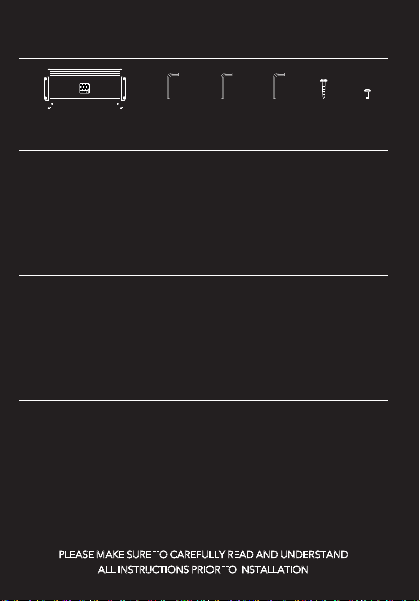
Package content
Practice Safe Sound!
X1
Available Accessories
PLEASE MAKE SURE TO CAREFULLY READ AND UNDERSTAND
ALL INSTRUCTIONS PRIOR TO INSTALLATION
- MPS-STKP stacking plates kit for MPS
Limited amplifiers
- MPS-R1 subwoofer remote level control
(MPS 1.1100 only)
- MPS-HL high-low level adaptor with 50-ohm
load resistor
The MPS Limited amplifiers are designed to work with a 12VDC electrical
system with negative ground. Use of this product in vehicles with positive
ground and/or voltages other than 12V may result in damage to the product
and/or vehicle and will void the warranty.The MPS Limited amplifiers are
designed to work with a 12VDC electrical system with negative ground. Use
of this product in vehicles with positive ground and/or voltages other than
12V may result in damage to the product and/or vehicle and will void the
warranty.
Studies have shown that continuous exposure to high sound pressure levels
from high power audio systems can lead to permanent hearing loss.
Additionally, high volume levels can obscure noises from outside your vehicle
such as emergency vehicles and horns. As a valued Morel customer, we urge
you to use common sense and practice restraint in the operation of this
product.
Precaution
X1
2mm
X4 X2X1
2.5mm
X1
4mm
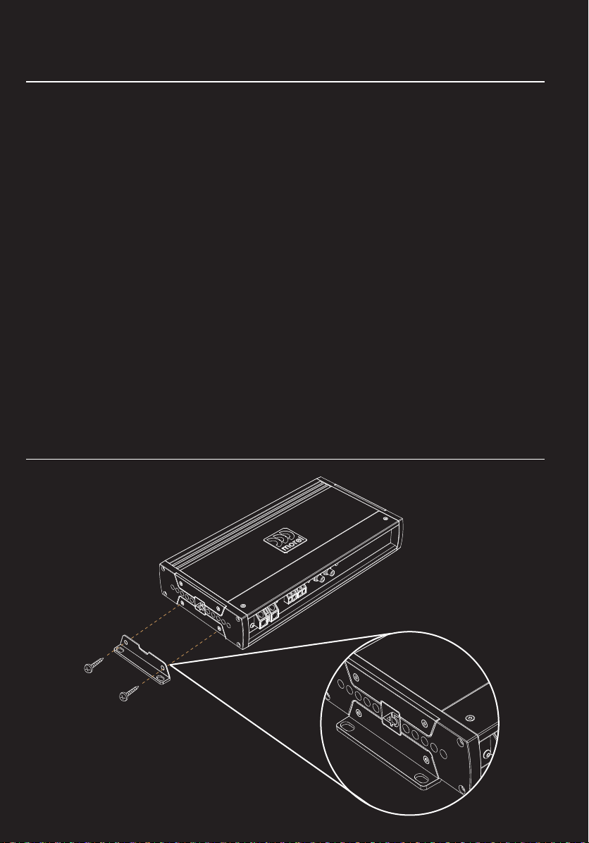
Mounting the amplifier
Mounting
Choose a location for the amplifier with ample ventilation for optimum
cooling performance. Be sure the amplifier is mounted with at least 2-inches
(50mm) of clearance around the chassis. Never fully enclose the amplifier in
a confined space without active ventilation. Also avoid mounting in areas of
direct sunlight and in areas of high vibration, such as a subwoofer
enclosure. Ideal mounting consists of the chassis being mounted with the
base of the amplifier parallel with the floor or perpendicular to the floor with
the fins of the heatsink facing upward for the most effective heat dissipation.
Your amplifier should always be installed in a location that will remain free
of moisture and dirt, and in a manner that does not interfere with any of the
electronics or safety gear of the vehicle.
For safety purposes, be sure to take the time to properly mount the
amplifier using suitable mounting hardware so the amplifier stays stationary
in the event of a collision or unforeseen circumstance.
Plate location for normal mounting

Plate location for discreet mount
Plate location for parcel shelf mounting
Mounting
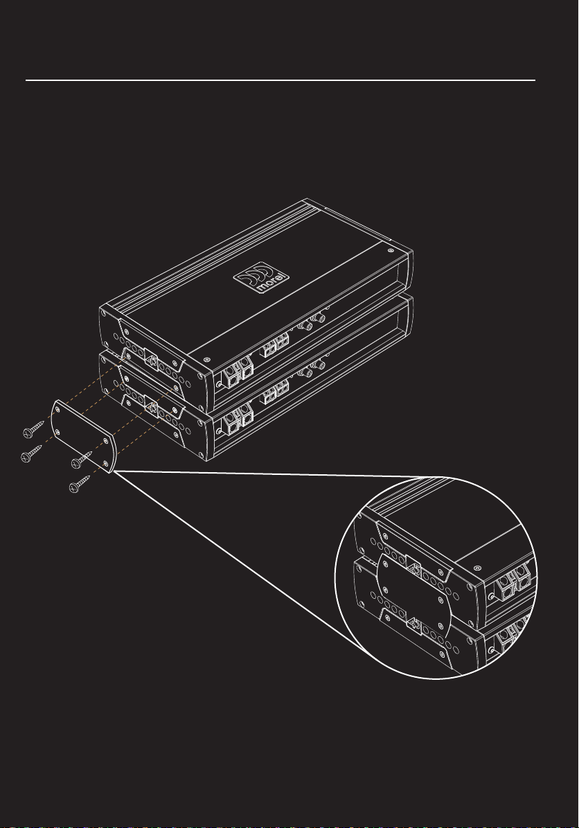
MPS-STKP stacking plates
The MPS Limited chassis also allow for amplifiers to be stacked using the
optional MPS-STKP stacking plates (see illustration). When using the
stacking plates, it is recommended the base amplifier be securely mounted
with a nut and bolt to a non-movable portion of the vehicle. Morel also
recommends no more than two amplifiers to be stacked for safety.
Mounting

Protection
Protection
Please note that there are no chassis mounted fuses on the MPS Limited
amplifiers. Instead these amplifiers use a sophisticated microprocessor
controlled protection circuit which enables the amplifier to optimize the
current flow coming into the power supply. This design reduces loss within
the circuitry, increases efficiency and improves sound dynamics of the
amplifier for the best listening experience. However, for the safety of you
and your vehicle, please follow instructions for installing an inline fuse (not
included) with your MPS Limited amplifier.

Planning and Installation
For best results, determine the best configuration of your new amplifier and
plan the wiring routes to ease installation and optimize performance.
• IMPORTANT! Disconnect the vehicle’s primary ground terminal from the battery
post prior to commencing the installation.
• Make sure the mounting location you chose for the amplifier does not interfere with
any functions of the vehicle mechanics and/or electronic devices. Also, be aware of
the locations of the gas tank, wiring harnesses, fuel and brake lines, and other vital
components of the vehicle prior to drilling any holes in the vehicle’s chassis.
• Select high quality signal cables and proper wire. It is highly recommended to use
100% OFC (oxygen free copper) power and speaker wire of proper size for best
performance and longevity of the product.
• Do not run power or audio cables on the exterior of the vehicle as this can result in
severe damage to the vehicle and person.
• Avoid running power and audio cables next to sensitive electronics within the
vehicle, and avoid crossing the signal cables with the power cables.
•Always use rubber grommets when running wire through metal walls or barriers. Use
loom to protect the cable from sharp edges or areas of high heat.
• Power amplifiers place an increased load on the electrical charging system. A
modern vehicle’s factory electrical system should be able to standup to the extra load
of an MPS Limited amplifier without concern. However, multiple amplifier systems can
draw excess current and create a strain on the electrical system. It is best to consult
your audio specialist for advise on whether or not it is necessary to upgrade your
electrical system to meet the demands of the audio system.
• Place an insulated in-line fuse holder (not included) of the appropriate current
capacity (see specifications) within 16 inches (40cm) of the battery positive (+)
terminal. This is to be connected to the (+) power cable connecting the amplifier. Only
install the fuse once the power cable has been secured to the amplifier.
• Locate a solid metal area close to the amplifier to connect the ground wire terminal.
Use the same gauge wire for ground as for the power wire. The length of the ground
wire should not exceed 36 inches (90cm) from the amplifier. To ensure a solid
connection, remove surface paint at the ground point prior to securing the connector
in place.

Power Status Indicator
The ON LED will illuminate blue when amplifier is properly powered on.
Protection Status Indicator
The PRT LED will illuminate red if the amplifier faults and goes into protect mode.
There are several reasons that could cause that amplifier fault including over
current, over or under voltage, short circuit,
thermal protection, or an internal error within the amplifier. If the fault is caused by
thermal protection, the amplifier will reset automatically once the heatsink has
cooled to about 70°C (160°F). If the PRT LED stays illuminated, the power status
LED will flash a code indicating the potential issue. See Fault Code at rear of
manual.
Negative Chassis Ground Connection
Connect an 8 gauge or larger OFC (oxygen-free copper) wire for ground (same
gauge used for +12V power wire). The length of the ground wire should not exceed
36 inches (90cm) from the amplifier. To ensure a solid connection, remove surface
paint at the ground point prior to securing the connector in place.
Remote Turn-On Connector
Connect to wire lead from a switched +12V source. This could be a remote turn on
lead from a head unit or switched ignition lead. If neither of these sources is
available, switch Turn On Mode to signal sensing or DC offset (see #10)
1
2
345 67 8 9
10
12
11
Rem
Offset Signal MIN MAX
Input
Level
Turn on
Mode
MIN MAX
Input
Level
CH1 CH2
High
Current High
Power
1
2
345 67 8 9
12
10 11
1
2
3
4
MPS 2.150 LIMITED - Features
Dieses Handbuch passt für folgende Modelle
2
Inhaltsverzeichnis


