mundoclima CL25620 Betriebsanleitung
MINI CHILLER INVERTER H6
English
CL25620 to CL25628
MUENR-H6 / MUENR-H6T
www.mundoclima.com
Installation & Owner's manual
and information requirements

1.2 Scope of this manual
READ THESE INSTRUCTIONS CAREFULLY BEFORE
INSTALLATION. KEEP THIS MANUAL IN A HANDY PLACE
FOR FUTURE REFERENCE.
IMPROPER INSTALLATION OR ATTACHMENT OF
EQUIPMENT OR ACCESSORIES COULD RESULT IN
ELECTRIC SHOCKS, SHORT-CIRCUITS, LEAKS, FIRE OR
OTHER DAMAGE TO THE EQUIPMENT. BE SURE TO
ONLY USE ACCESSORIES MADE BY THE SUPPLIER
WHICH ARE SPECIFICALLY DESIGNED FOR USE WITH
THE EQUIPMENT AND HAVE INSTALLATION DONE BY A
PROFESSIONAL
ALL ACTIVITIES DESCRIBED IN THIS MANUAL SHALL BE
CARRIED OUT BY A LICENSED TECHNICIAN.
BE SURE TO WEAR ADEQUATE PERSONAL
PROTECTION SUCH AS GLOVES AND SAFETY GLASSES
WHEN PERFORMING INSTALLATION, MAINTENANCE
OR SERVICE TO THE UNIT.
IF UNSURE OF INSTALLATION PROCEDURES OR USE,
CONTACT YOUR DEALER FOR GUIDANCE
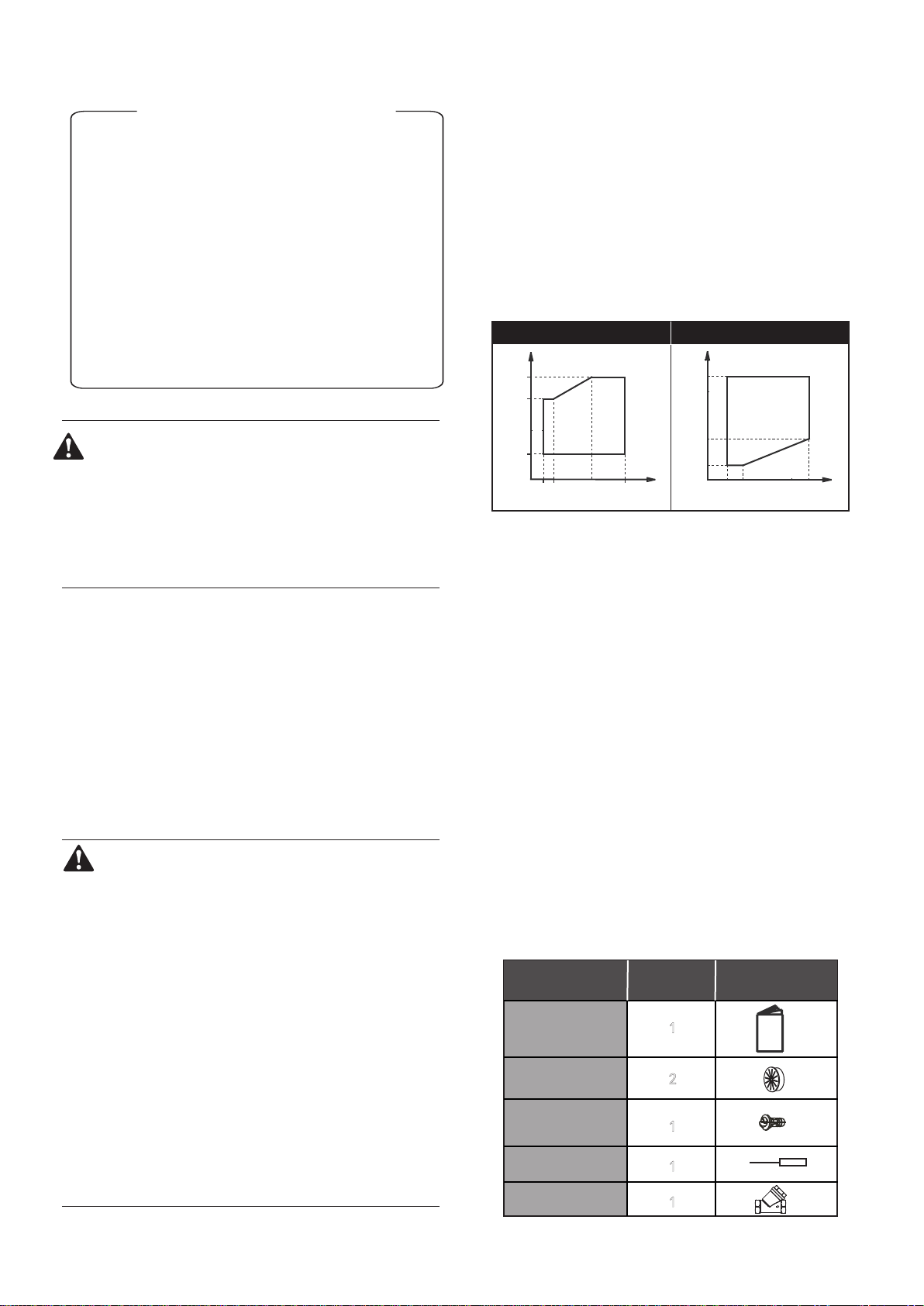
■ Operation range
(*) The unit can not operate in cold weather conditions below -15℃. If
it is necessary to operate, an external auxiliary heat source must
be added as a backup heater. the backup heater also serves as a
backup in case of malfunctioning of the unit and for freeze
ptrotection of the outside water piping during winter time.
These models have an antifreeze function that allows the use of
heat pumps to keep the water system free from freezing under all
conditions. If there is an accident or intentional power outage, it is
recommended to use ethylene glycol.
2. ACCESSORIES
2.1 Accessories supplied with the unit
1.1 General information
■
These units are used for both heating and cooling applications.
They can be combined with fan coil units, floor heating
applications (connect the mixed station), low temperature high
efficiency radiators (field supply).
■
The host unit controller is standard supplied with the unit to control
the system.
■ A wired remote controller can also be used to control the system
(Optional).
1. INTRODUCTION
CONTENTS PAGE
1. INTRODUCTION................................................................... 1
2. ACCESSORIES..................................................................... 1
3. SAFETY CONSIDERATIONS............................................... 2
4. OVERVIEW OF THE UNIT.................................................... 3
5. UNIT INSTALLATION........................................................... 11
6 START-UP AND CONFIGURATION.................................... 25
7. THE HOST UNIT CONTROLLER ELUCIDATION............... 27
8. TROUBLE SHOOTING......................................................... 31
9. IMPORTANT INFORMATION FOR THE USED
REFRIGERANT..................................................................... 32
10. MAIN PARAMETERS......................................................... 33
HEATING MODE
DELIVERY WATER TEMPERATURE
OUTSIDE AIR TEMPERATURE
35 54
-15
0
27
t(°C)
t(°C)
40
2
1
1
1
Shape
Qty.Unit
Outflow connecting
tube (for the chassis)
Straight screwdriver
1
Y-shaped filter
Installation &
Owner’s Manual
Rubber ring for wires
(only 10~16kW)
COOLING MODE
DELIVERY WATER TEMPERATURE
OUTSIDE AIR TEMPERATURE
4 7 15 20
-5
35
46
t(°C)
t(°C)
This installation & ow
ner's man
ual does not include the selection
procedure and water system design procedure. Only some
precautions and tips and tricks about the design of the water circuit
are given in a separate chapter of this manual. Once the selection is
done and the water system is designed, this manual describes the
procedures for handing, installing and connecting the unit, This
manual has been prepared to ensure adequate maintenance of the
unit, and it will provide help if problems occur.
This unit is designed to cool/heat water and must be
used in applications compatible with its performance
characteristics, i.e. residential or commercial applications
combined with a fan coil unit, low temperature radiators
and underfloor heating. It should never be used for
underfloor cooling, as doing so may damage the plate
heat exchanger.
1
3. SAFETY CONSIDERATIONS
The precautions listed here are divided into the following types.
They are quite important, so be sure to follow them carefully.
Meanings of DANGER, WARNING, CAUTION and NOTE symbols.
DANGER
Indicates an imminently hazardous situation which if not
avoided, will result in death or serious injury.
WARNING
Indicates a potentially hazardous situation which if not
avoided, could result in death or serious injury.
CAUTION
Indicates a potentially hazardous situation which, if not
avoided, may result in minor or moderate injury. It is also
used to alert against unsafe practices.
NOTE
Indicates situations that could only result in accidental
equipment or property damage.
■ Before touching electric terminal parts, turn off power switch.
■ When service panels are removed, live parts can be easily
touched by accident.
Never leave the unit unattended during installation or servicing
when the service panel is removed.
■ Do not touch water pipes during and immediately after operation
as the pipes may be hot and could burn your hand. To avoid injury,
give the piping time to return to normal temperature or be sure to
wear protective gloves.
■ Do not touch any switch with wet fingers. Touching a switch with
wet fingers can cause electrical shock.
■ Before touching electrical parts, turn off all applicable power to
the unit.
DANGER
WARNING
■ Tear apart and throw away plastic packaging bags so that children
will not play with them.
Children playing with plastic bags face danger of death by
suffocation.
■ Safely dispose of packing materials such as nails and other metal
or wood parts that could cause injuries.
■ Ask your dealer or qualified personnel to perform installation work
in accordance with this manual. Do not install the unit yourself.
Improper installation could result in water leakage, electric shocks
or fire
■ Be sure to use only specified accessories and parts for installation
work.
Failure to use specified parts may result in water leakage, electric
shocks, fire, or the unit falling from its mount.
■ Install the unit on a foundation that can withstand its weight.
■ Insufficient physical strength may cause the equipment to fall and
possible injury
■ Perform specified installation work with full consideration of strong
wind, hurricanes, or earthquakes.
Improper installation work may result in accidents due to equipment
falling.
■ Make certain that all electrical work is carried out by qualified
ersonnel according to the local laws and regulations and this
manual using a separate circuit.
Insufficient capacity of the power supply circuit or improper electrical
construction may lead to electric shocks or fire.
■ Be sure to install a ground fault circuit interrupter according to local
laws and regulations.
Failure to install a ground fault circuit interrupter may cause electric
shocks and fire.
■ Make sure all wiring is secure. Use the specified wires and ensure
that terminal connections or wires are protected from water and
other adverse external forces.
Incomplete connection or affixing may cause a fire.
■ When wiring the power supply, form the wires so that the front panel
can be securely fastened.
If the front panel is not in place there could be overheating of the
terminals, electric shocks or fire.
■ After completing the installation work, check to make sure that there
is no refrigerant leakage.
■ Never directly touch any leaking refrigerant as it could cause severe
frostbite.
■ Do not touch the refrigerant pipes during and immediately after
operation as the refrigerant pipes may be hot or cold, depending on
the condition of the refrigerant flowing through the refrigerant piping,
compressor and other refrigerant cycle parts. Burns or frostbite are
possible if you touch the refrigerant pipes. To avoid injury, give the
pipes time to return to normal temperature or, if you must
touchthembe sure to wear protective gloves.
■ Do not touch the internal parts (pump, etc.) during and immediately
after operation.
Touching the internal parts can cause burns. To avoid injury, give
the internal parts time to return to normal temperature or, if you must
touch them, be sure to wear protective gloves.
CAUTION
■ Ground the unit.
Grounding resistance should be according to local laws and
regulations
Do not connect the ground wire to gas or water pipes,
lightning conductors or telephone ground wires.
Incomplete grounding may cause electric shocks.
a) Gas pipes.
Fire or an explosion might occur if the gas leaks.
b) Water pipes.
Hard vinyl tubes are not effective grounds.
c) Lightning conductors or telephone ground wires.
Electrical threshold may rise abnormally if struck by a lightning bolt.
■ Install the power wire at least 3 feet (1 meter) away from
televisions or radios to prevent interference or noise. (Depending
on the radio waves, a distance of 3 feet (1 meter) may not be
sufficient to eliminate the noise.)
■ Do not wash the unit. This may cause electric shocks or fire. The
appliance must be installed in accordance with national wiring
regulations. If the supply cord is damaged, it must be replaced by
the manufacturer, its service agent or similarly qualified persons in
order to avoid a hazard.
■ Do not install the unit in the following places:
a) Where there is mist of mineral oil, oil spray or vapors.
Plastic parts may deteriorate, and cause them to come
loose or water to leak.
b) Where corrosive gases (such as sulphurous acid gas) are
produced.
Where corrosion of copper pipes or soldered parts may cause
refrigerant to leak.
2

c) Where there is machinery which emits electromagnetic waves.
Electromagnetic waves can disturb the control system and
cause equipment malfunction.
d) Where flammable gases may leak, where carbon fiber or
ignitable dust is suspended in the air or where volatile
flammables such as paint thinner or gasoline are handled.
These types of gases might cause a fire.
e) Where the air contains high levels of salt such as near the
ocean.
f) Where voltage fluctuates a lot, such as in factories.
g) In vehicles or vessels.
h) Where acidic or alkaline vapors are present.
■ This appliance can be used by children 8 years old and above and
persons with reduced physical, sensory or mental capabilities or
lack of experience and knowledge if they are supervised or given
instruction on using the unit in a safe manner and understand the
hazards involved. Children should not play with the unit. Cleaning
and user maintenance should not be done by children without
supervision.
■ Children should be supervised to ensure that they do not play with
the appliance.
■ If the supply cord is damaged, it must be replaced by the manufaturer
or its service agent or a similarly qualified person.
■ DISPOSAL: Do not dispose this product as unsorted municipal
waste. Collection of such waste seperatelly for special treatment is
necessary.
Do not dispose of electrical appliances as municipal waste, use
seperate collection facilities.
Contact your local goverment for information regarding the
collection systems available.
If electrical appliances are disposed of in landfills or dumps,
hazardous substance can leak into the groudwater and get into the
food chain, damaging your health and well-being.
■ The wiring must be performed by professional technicians in
accordance with national wiring regulation and this circuit diagram.
An all-pole disconnection device which has at least 3mm
seperation distance in all pole and a residualcurrent device(RCD)
with the rating not exceeding 30mA shall be incorporated in the
fixed wiring according to the national rule.
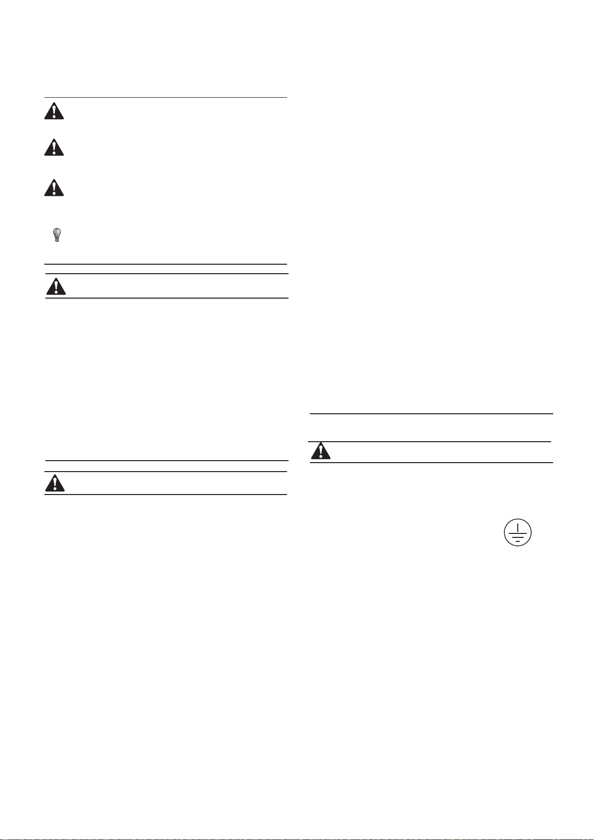
1 Operation panel
2 4-ways valve
3 Storage tank
4 Pump
5 Electric expansive valve
6 Compressor
7 Air purge valve
8 Electrical control box
9 Water manometer
10 Expansion tank
11 Plate heat exchanger
12 Condenser
13 Axial-flow fan
14 Adapter substitute
(accessory)
15 Security discharge
16 Auto-water replenishing
valve (accessory)
17 Water flow switch
18 High pressure switch
19 Low pressure switch
1
211
12
13
3
4
5
6
7
8
9
10
14
15
16
17
18
19
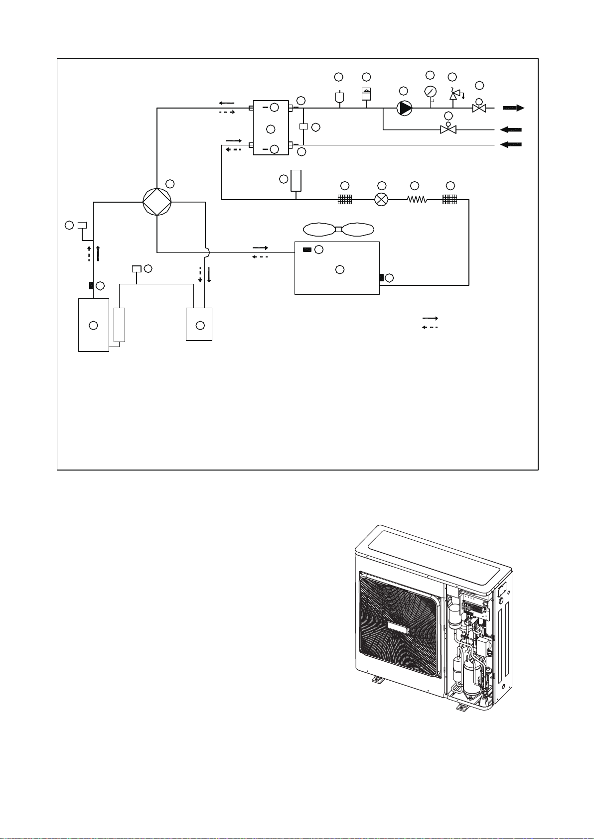
4. OVERVIEW OF THE UNIT
1 Operation panel
2 Water manometer
3 Air purge valve
4 Axial-flow fan
5 Differential pressure switch
6 Condenser
7 Accumulater
8 Security discharge
9 Electric expansive valve
10 Plate heat exchanger
11 Electrical control box
12 High pressure switch
13 4-ways valve
14 Expansion tank
15 Pump
16 Low pressure switch
17 Storage tank
18 Compressor
19 Auto-water replenishing
valve
1
5
7
8
9
10
11
12
13
14
15
16
17
18
19
2
3
4
6
4.1 Main parts of the unit
4.2 Unit connections
5/7kW
10~16kW
1 Water inlet
2 Water outlet
3 Auto-watet replenishing orifice
4 Water outlet of safety Valve
5 Wire hole
1
3
2
4
5
3
4.3 Refrigerant cycle
4.4 Electrical control box introduce
4.4.1 5/7kW (1-phase)
The electrical control box is located inside the unit at the top of
the technical compartment where the various components
of the refrigerant circuit are also to be found.
To access the electrical panel,remove the front panel of
the unit by undoing the screws.
PL
PH
1 3
52
2
4
7
88
5
9
62
01
2
1
31
41
51
61
71
8
1
gnilooC
gnita
e
H
91 0
2
12
22 32
42
A
F
11
6
1 Compressor
2 4-Way Valve
3 Gas-liquid Separator
4 Air Side Heat Exchanger (condenser)
5 Electronic Expansion Valve
6 Capillary (only 5/7kW)
7 Storage Tank
8 Strainer
9 Water Side Heat Exchanger
(Plate Heat Exchange)
10 Differential Pressure Switch (only 10~16kW)
11 Flow Switch (only 5/7kW)
12 Thermistor For Discharge Temperature
13 Thermistor For Outdoor Temperature
14 Thermistor For Evaporation In Heating
(Thermistor For Condenser In Cooling)
15 Thermistor For Plate Heat Exchange 1
16 Thermistor For Plate Heat Exchange 2
17 Thermistor For Water Outlet
18 Thermistor For Water Inlet
19 Air purge Valve
20 Expansion Tank
21 Circulating Pump
22 Water manometer
23 Safety Valve
24 Auto-watet replenishing valve
25 High Pressure Switch
26 Low Pressure Switch
4
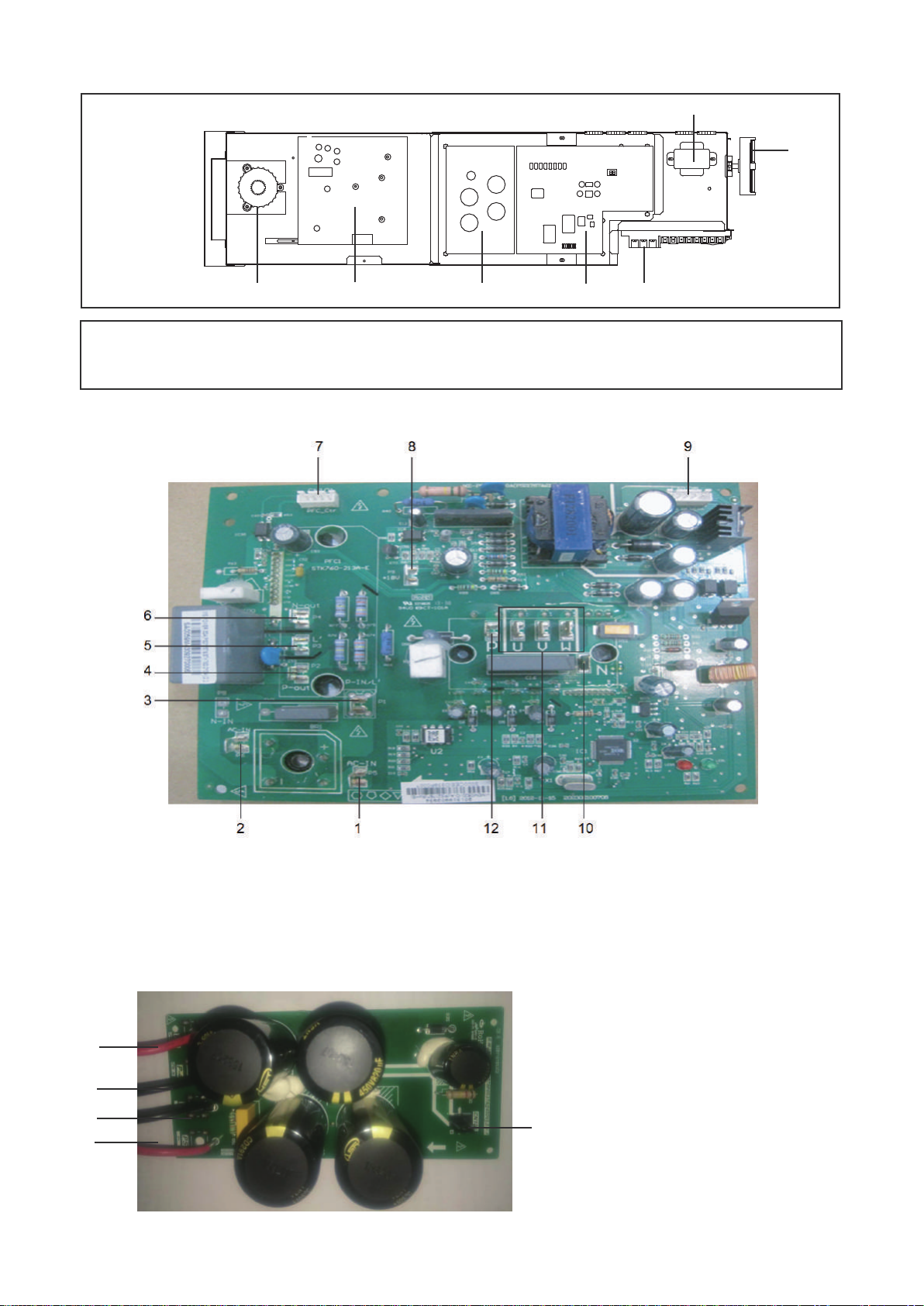
2. PFC&IPM module board (The picture is for reference only)
1.Input rectifier bridge port 1
2.Input rectifier bridge port 2
3.PFC inductance port 1
4.P-OUT
5.PFC inductance port 2
6.N-OUT
7.PFC control port
8.+18V port
9.IPDU communication port
10.IPM power port N
11.Compressor connection port U/V/W
12.IPM power port P
3. DC filter board (The picture is for reference only)
1.IPM Power supply P
2.IPM Power supply N
3.PFC output power N
4.PFC output power P
5.DC 380V (DC fan power supply port)
1. ELECTRICAL PANEL LAYOUT
① Main control board
② DC filter board
③ IPM & PFC module board
④ FC inductance
⑤ Transformer
⑥ Display board
⑦ Customer connection terminal
④ ③ ② ① ⑦
⑤
⑥
(The picture below shows the position of the diagram, please participate in the concrete photos)
5
4
1
2
3
5
4. Main control board (The picture is for reference only)
1.Power L
2.Power N
3.Preliminary charging relay (rectifier bridge input port 1)
4.Input rectifier bridge line (rectifier bridge input port 2)
5.5A fuse
6.To IPDU
7.To PFC
8.Solenoid valve (Reserve)
9.Electric heater of plate heat exchanger
10.Electric heater of compressor
11.Pump
12.Electric heater of exhaust valve
13.Electric heater of water flow switch
14.4-way valve
15.Additional pump/Remote alarm port
16.Transformer input
17.Electronic expansion valve
18.DC fan power supply port
19.DC fan port
20.Remote control port
21.Force cooling switch
22.Parameter checking switch
23.Tin/Tout/Tb1 temperature sensor
24.Discharge temperature sensor (Tp)
25.1 Outlet of outdoor heat exchanger temperature sensor (T3)
25.2 Ambient temperature sensor(T4)
26.1 Low pressure switch
26.2 High pressure switch
27.Operation and display panel port
28.Water flow switch
29.Transformer output
30.Wired controller port
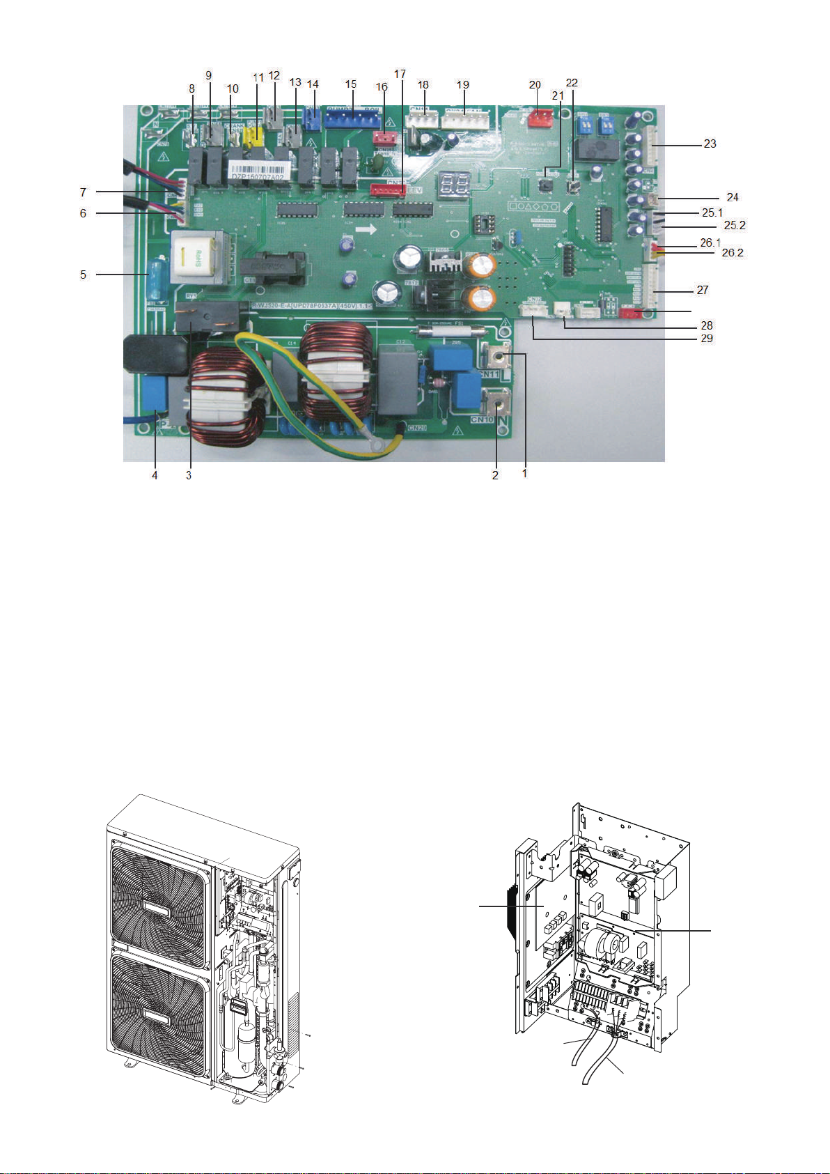
4.4.2 10~12kW (1-phase)
Remove the inspection panel by unscrewing the five screws. The
electric control box is located inside the unit at the top of the technical
components.
1. Use grommet A for the electrical power cable and grommet B
for the other external wires.
(The picture below shows the position of the diagram, please
participate in the concrete photos)
A
B
①
②
① Main control board ② PFC&IPM module board
30
6
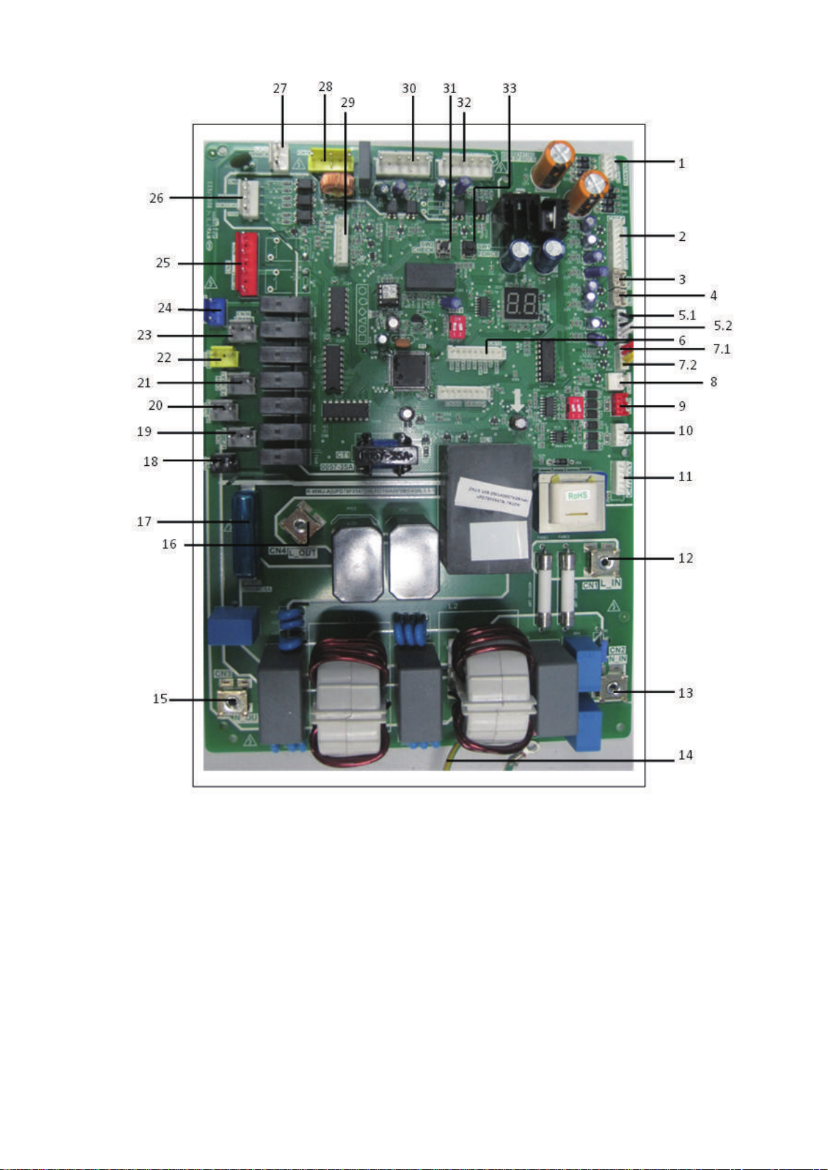
2. Main control board (The picture is for reference only)
1.Transformer output port
2.Tin/Tb1/Tout/Tb2 temperature sensor port
Note: Tin: water inlet temp. Tout: water outlet temp.
Tb1: Temp. 1 of plate heat exchanger
Tb2: Temp.2 of plate heat exchanger
3. Radiator temperature sensor port(Reserved) (T6)
4. Discharge temperature sensor port
5.1 Outlet of outdoor heat exchanger temp. sensor port(T3)
5.2 Ambient temp. sensor port (T4)
6.Operation and display panel port
7.1 Low pressure switch
7.2 High pressure switch
8.Differential pressure valve port
9.Factory debug port
10.Wired controller port
11.Electric expansion valve port
12.Power supply input port L
13.Power supply input port N
14.Ground wire
15.Rectifier bridge input port N
16. Rectifier bridge input port L
17. 8A fuse tube
18. Solenoid valve port (Reserved)
19. Exhaust valve electric heater port
20. Plate heat exchanger electric heater port
21. Flow switch electric heater port
22. Built-in water pump port
23. Compressor electric heater port
24. 4-way valve port
25. External pump/Remote alarm port
26. Remote control port
27. Transformer input port
28. P/N/+15V port
29. Communication port between IPDU and main PCB
30. Down DC fan port
31. Check touch switch
32. Up DC fan port
33. Force-cooling touch switch
7
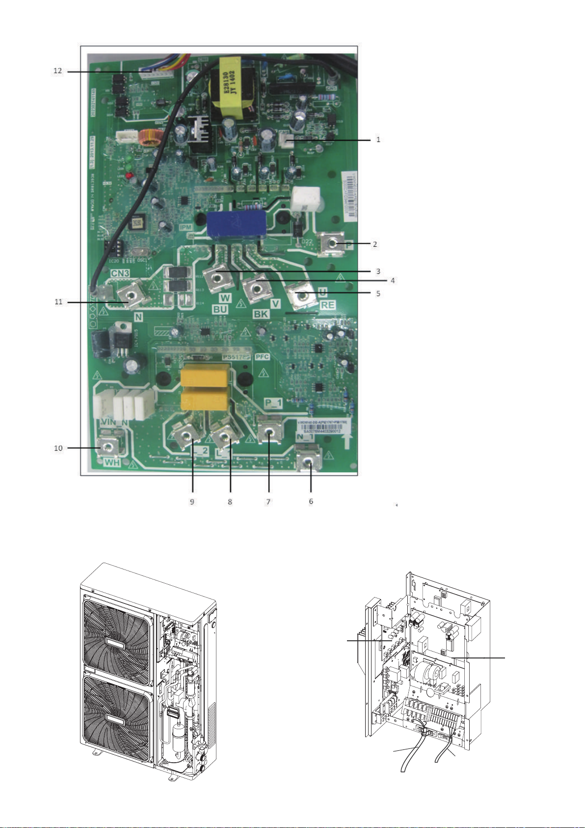
3. PFC&IPM module board (The picture is for reference only)
1. +18V output port
2. Input Port P for IPM
3. Power supply port W
of the compressor
4. Power supply port V
of the compressor
5. Power supply port W
of the compressor
6. PFC output N
7. PFC output P
8. PFC inductance port L_1
9. PFC inductance port L_2
10. PFC input N
11. IPM input N
12. Communication port to
main control board
A
B
4.4.3 12~16kW (3-phase)
Remove the inspection panel by unscrewing the five screws.
The electric control box is located inside the unit at the top of the
technical components.
1. Use grommet A for the electrical power cable and grommet B for
the other external wires.
(The picture below shows the position of the diagram, please
participate in the concrete photos)
①
②
① Main control board ② IPM module board
8
Dieses Handbuch passt für folgende Modelle
16
Inhaltsverzeichnis
Andere mundoclima Wechselrichter Handbücher

mundoclima
mundoclima MUENR-H12 Betriebsanleitung

mundoclima
mundoclima H11 Series Bedienungsanleitung

mundoclima
mundoclima MUPR-H7 Bedienungsanleitung

mundoclima
mundoclima H11 Series Montageanleitung

mundoclima
mundoclima H3 Series Bedienungsanleitung

mundoclima
mundoclima MUENR-H6 Series Betriebsanleitung

mundoclima
mundoclima H6 Series Bedienungsanleitung


