NCS NCS-C250C Bedienungsanleitung

NCS-C250C
INSTRUCTION MANUAL
Rev J
New Communications Solutions, LLC
536 Valley Mist Trace
Suite 101
Norcross, Georgia 30092
Toll Free Tel. & Fax : 888- 883-5788
Email : [email protected]
Web Site: www.ncsradio.com

Revision History
Rev Description Date Approved
A 9/8/04 CIF
B 01/21/05 CIF
C Add TOC. General Cleanup 06/06/05 CIF
D CO-C250MANUAL-001 08/08/05 CIF
Combine Option Manual 10/15/05 CIF
F Add S/N, VOX/COR ID, MIC INFO 10/14/06 CIF
G Change Default Shunts 06/22/07 CIF
H Change to B model, impedance jumper
clarification.
10/23/08 CIF
I Change to C model. 08/01/09 CIF
J Corrected Missing Tables 09/14/10 CIF
FACTORY INSTALLED OPTION
IDENTIFICATION TABLE
The Serial Number Label located on the bottom of the unit indicates which Options are
installed according to the following chart:
Option COR HookSwitch Multicast Sidetone
M00
M04 X
M05 X
M06 X X
M08 X
M09 X X
M10 X X
M11 X X X
M12 X
M13 X X
M14 X X
M15 X X
M16 X X X
M17 X X X
M18 X X X
M19 X X X X
NOTE: The COR and Hookswi ch Op ions require ha an Op ion Board be ins alled in he C250C a
he fac ory.
NOTE: If a microphone was ordered with this unit, it has been factory setup
for the supplied microphone listed below.
Microphone: _________________________________
(To change microphone se up, see page 9.)
(circle Busy De ec ion mode for each RAD por ))
COR: RAD1 RAD2 RAD3 RAD4
Model: ___________________________________ VOX: RAD1 RAD2 RAD3 RAD4
Serial Number: ____________________________
NCS-C250C Instruction Manual Rev J Copyright © 2004-2010 New Communications Solutions, LLC
2

Table of Contents
1.0 Introduction....................................................................................................4
2.0 Safety Information..........................................................................................5
3.0 Accessory Kit.................................................................................................6
4.0 Front Panel Controls.......................................................................................6
5.0 Radio, Speaker and Microphone Requirements.............................................7
6.0 Power Supply..................................................................................................8
7.0 Microphone Setup..........................................................................................9
8.0 Rear Panel Connections................................................................................12
9.0 Radio Interface Cables.................................................................................14
10.0 Adjustments................................................................................................15
11.0 Operating the C250C .................................................................................18
12.0 C250C Option Board..................................................................................20
13.0 Block Diagram............................................................................................24
14.0 Troubleshooting..........................................................................................25
15.0 Contacting NCS..........................................................................................26
16.0 C250C Specifications ..............................................................................27
NCS-C250C Instruction Manual Rev J Copyright © 2004-2010 New Communications Solutions, LLC
3

1.0 Introduction
The C250C provides a me hod of swi ching one microphone or headse and wo speakers o mul iple
radios.
Nearly any dynamic or elec re microphone can be used wi h he C250C . Pin assignmen s,
impedance, level, and elec re mic elemen vol age (phan om vol age) are jumper selec able. A
DTMF microphone can be used for con rolling all fron panel swi ch func ions.
Separa e speaker ou pu s are provided for Selec ed and Unselec ed audio wi h individual volume
con rols and mu e func ions.
A high power PA speaker ou pu and a voice-opera ed cross-band repea er/range ex ender suppor
ou -of-vehicle opera ion.
All swi ches are illumina ed for low ligh or nigh opera ion and LED indica or brigh ness is
au oma ically adjus ed based on ambien ligh o provide easy day or nigh viewing of uni s a us.
NCS-C250C Instruction Manual Rev J Copyright © 2004-2010 New Communications Solutions, LLC
4
Typical Application

2.0 Safety Information
The C250C is an elec rical device requiring appropria e safe y measures during ins alla ion and
opera ion. The following safe y precau ions should be observed:
•When connec ing he uni o a DC power source, a minimum wire size of 18 AWG should be
used. When using in a mobile environmen , au omo ive grade wire should be used.
•Do no rou e cables or wires hrough areas ha may cause he insula ion o be worn resul ing
in shor ing of he wires o ground or o each o her.
•Always replace fuses wi h he ra ings specified by he manufac urer.
•Do no place your ears in close proximi y o he local speakers or PA speaker a high volume
se ings. Your hearing could be impaired as a resul .
•Do no a emp o opera e his equipmen while driving a vehicle. For safe y, pull over o he
side of he road when making adjus men s.
•NEVER connec his device o an AC vol age source. Dea h or injury could occur and/or he
uni can be badly damaged. Connec his device only o a DC power source wi h a vol age
ou pu of 12-15 vol s and a curren capabili y of a leas 2A.
NCS-C250C Instruction Manual Rev J Copyright © 2004-2010 New Communications Solutions, LLC
5

3.0 Accessory Kit
An Accessory Ki is packed wi h he C250C . The following i ems are included in he Ki :
Item Quantity Description
Power Cable, DC 1 10 foo cable for connec ing C250C o DC power source.
Ki , Speaker Connec or 1 Consis s of 1 Plug Housing and 10 each con ac s for 18-22
AWG and 22-26 AWG speaker wire.
Fuse, 5x20mm 2 Spare 3A fuses.
Shun s, Black 30 Used o program he microphone pins.
Moun ing Fee 4 Used for able- op ins alla ion.
Clamp, Power Connec or 1 Used o clamp he C250C power pig ail connec or o he
DC Power Cable.
.0 Front Panel Controls
I em Descrip ion
1 Power Swi ch wi h Red LED Indica or- La ching
2 Radio Selec Swi ches wi h Red Selec ed and Green Busy Indica ors, Momen ary
3 PA/Repea er selec ion swi ch wi h Red RPT and Green PA Indica ors, Momen ary
4 Mu e Func ion Swi ches wi h Yellow Indica ors, Momen ary
5 Volume Con rols for Selec ed Audio and PA (SEL/PA) and Unselec ed Audio (UNSEL)
6 Fron Panel Microphone Jack , RJ45 Modular
NCS-C250C Instruction Manual Rev J Copyright © 2004-2010 New Communications Solutions, LLC
6
1 2 3 4 5
6

5.0 Radio, Speaker and Microphone Requirements
5.1 Radio
5.1.1 Receive Audio
Receive Audio inpu levels from he radio should be from 200mVp-p o
500mVp-p. The Busy ligh s ac iva e a approxima ely 150mV. Receive
audio inpu levels are normally adjus ed using he Volume Con rols on he
radios.
CAUTION: When using radios with bridged audio speaker outputs,
connect only one of the speaker output lines to the C250C . Leave the
other speaker output line disconnected and preferably insulated with
shrink tubing. The receive audio return path is via the ground
connection between the radio and the C250C .
5.1.2 Transmi Audio
Transmi audio levels are separa ely adjus able for each radio and sufficien
gain is available o drive nearly any radio.
5.1.3 PTT
PTT is via an Open-Drain ou pu . This signal pulls he PTT line of he radio
low and will key any radio wi h a low- rue PTT requiremen . Maximum
swi ching capaci y of he PTT ou pu is 100V, 1.5A DC.
Some radios use a single line o combine PTT and o her con rol func ions.
These radios may no be compa ible wi h he PTT circui ry of he C250C .
Con ac NCS for informa ion on use of hese radios.
5.2 Speaker
The C250C was designed o drive speakers of 4-8 Ohms nominal impedance. Maximum
power ou pu is achieved wi h 4 Ohm speakers. Speaker power ra ings should be
chosen according o he speaker impedance as shown in his char :
Speaker Impedance
(Ohms)
Minimum Power Rating
(Watts-rms)
Selec ed 4 Ω4
8 Ω2
Unselec ed 4 Ω4
8 Ω2
PA 4 Ω16
8 Ω8
CAUTION: NEVER ground either side of the PA speaker output
terminals. Doing so may damage the audio amplifier in the C250C .
5.3 Microphone
The adjus able amplifier in he C250C allows mos any dynamic or elec re microphone
o be used. Typical inpu level from he microphone should be in he range 50mV-
250mV.
NCS-C250C Instruction Manual Rev J Copyright © 2004-2010 New Communications Solutions, LLC
7
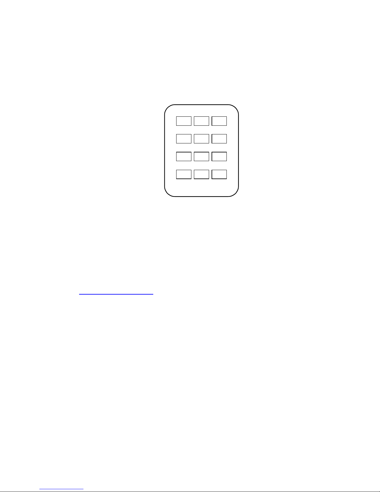
When using a microphone wi h DTMF capabili y, he DTMF bu ons can be used ins ead
of or in addi ion o he fron panel con rols. For DTMF con rol, he DTMF ones mus be
genera ed in he microphone. The audio level of he ones should no exceed normal
voice level. NOTE: The DTMF Option must be enabled-see Section 10.3. The
diagram below shows he DTMF bu ons ha correspond o he fron panel con rols on
he C250C . No e ha RAD5-RAD8 are only used wi h configura ions using a C250C
wi h a C251 Expansion Uni as an 8 radio swi cher.
1
#0
987
65
32
*
RAD1
UNSEL
MUTE
AUTO
MUTE
SEL
MUTE
PA/RPT
RAD
RAD3RAD2
RAD5 RAD6
RAD7 RAD8
6.0 Power Supply
6.1 Power Requirements
The NCS-C250C will opera e wi h any 9-16 VDC power supply capable of providing a
leas 2A con inuous.
6.2 Power Connection
Power is supplied o he pig ail on he rear of he uni . The connec or is an Anderson
Powerpole PP-15. As par of he accessory ki , a 10 foo power cable is supplied wi h a
ma ing connec or a ached. Connec he power cable o a 9-16 VDC source capable of
supplying a leas 2A. Addi ional connec ors are available from Powerwerx (web si e:
h p://www.powerwerx.com, elephone: 714-570-3303)
6.3 Polarity
Power cable polari y is: Red = +, Black = - (or chassis).
6. Fusing
Bo h power supply lines are fused wi h fas -ac ing 3A 5x20 mm fuses (Wickmann USA
series 191 or equivalen ).
6.5 Using an AC Power Supply
The C250C can be opera ed from any well-regula ed 9-16 VDC power supply capable of
delivering a minimum of 2 Amperes. Vol ages higher han 16V may resul in damage o
he circui ry.
6.6 Power Cable Clamp
The Power Cable Clamp is used o keep he Power Cable from separa ing from he
Power Pig ail in Mobile use.
NCS-C250C Instruction Manual Rev J Copyright © 2004-2010 New Communications Solutions, LLC
8

7.0 Microphone Setup
The main circui board inside he C250C has provisions for se ing up he microphone
func ions. To se up hese func ions, remove he cover of he C250C and refer o he
diagram below for he loca ions of se ings and adjus men s.
Main Circuit Board
7.1 Front and Rear Panel Microphone Connections
The microphone connec ors on he fron and rear panels accep s andard 8-pin RJ-45
modular plugs. Ei her connec or can be used. The fron and rear connec ors are connec ed
in parallel and bo h use he same pin programming. The func ion of each pin is
programmable using he jumper blocks on he main circui board.
7.1.1 Microphone Pinou s
The RJ45 modular plug pin numbering used on his uni is shown below:
NCS-C250C Instruction Manual Rev J Copyright © 2004-2010 New Communications Solutions, LLC
9
Radio Transmit
Audio Level
Adjustments
Microphone Setup
Jumpers
Microphone Level
Adjustment
Microphone Level
Indicator L Ds
Front of Board

7.1.2 Programming he Microphone Connec ors
Programming he microphone connec ors is accomplished by se ing he microphone
connec or pin func ions, selec ing he impedance level and connec ing a vol age
supply pin if using an elec re microphone elemen
The diagram below shows he Microphone Se up Area of he main circui board.
Refer o i for he following s eps.
.
Microphone Setup Area
To program he func ions of he pins on he microphone connec ors, use he shun s
supplied in he accessory ki o jumper he appropria e microphone pin numbers o
he corresponding signals on he MIC CONN PIN jumper blocks.
For example, o program he microphone shown in he following char , ins all he PIN
SELECT shun s as shown. NOTE: These shun s are shown in he fac ory defaul
posi ions.
NCS-C250C Instruction Manual Rev J Copyright © 2004-2010 New Communications Solutions, LLC
10
Default Microphone Pin-out
MIC
Pin
Shunt
Row Signal Name
Pin 1 ------ N/C
Pin 2 ------ N/C
Pin 3 ------ N/C
Pin 4 J2 MIC Audio
Pin 5 J4 GND
Pin 6 J3 PTT
Pin 7 ------ N/C
Pin 8 ------ N/C
Mic Impedance and
Attenuation Jumper
lectret Voltage Jumper
Inhaltsverzeichnis


