NetAlert NetMeter Bedienungsanleitung
TMTM
NetMeter for
Patent Pending
DeviceNet
Users Guide
P/N 715-0016 V1.2

Essentials
DeviceNet Cable Essentials
AutoSearch Mode
Read this first!
DeviceNet cable
has five wires
inside. Each has a
specific purpose
which is referenced
in this manual.
CANL
(messages)
Shield
V-
(power)
V+
(power)
CANH
(messages)
AutoSearch mode saves you time by finding the network
measurements that exceed acceptable limits. It works by
examining all measurements and then pinpointing any
that exceed or are close to specified limits. For
each problem measurement NetMeter indicates the
measurement's switch position number in the upper left
corner of the display. Rotate the selector switch to the
indicated setting to view related measurements.
NetMeter requires 2 ‘AA’ Alkaline batteries for viewing
measurements offline. NetMeter must be plugged into a
powered network to get most measurements. NetMeter
will run off DeviceNet network power, even without
batteries installed. Remember to install batteries if you
plan to use the Lock and offline viewing features.
How to Use AutoSearch ...
1. Make sure the Lock switch is in the “Run” position and
turn the selector switch to AutoSearch
2. If you see - all measurements are within limits.
3. If you see or then read the display like this ...
“Switch setting <Setting #>, <MIN> or <MAX> and/or
<P-P> is close to or Exceeds the spec limits.”
Then press and repeat the process for the next
bad/marginal value.To get more detail, turn the
selector switch to the indicated position and use the
buttons to access related measurements.
2
1

How to use this manual
This is a reference manual for the DeviceNet NetMeter
(DN-MTR). For each NetMeter switch position you will
find a page explaining the measurements available, and
suggested actions and/or remedies if your network is not
healthy.
On each page you’ll find:
The minimum shield
voltage recorded
since the NetMeter
was plugged in or
reset is -3.5V.
x1
V
250
MIN
x5
Displays the
maximum frame rate
per second on the
network since the
NetMeter was
plugged in or reset.
LCD display
# of times to push the advance button after moving
the selector switch to display this measurement.
Description
Push the Advance
button
You can view this measurement for each active
device by pressing the or buttons.
Pressing and at the same time displays
the overall network measurement again.
The measured value
exceeds the positive or
negative input range.
No measurement taken
(see additional details for
specific measurements).
Special Conditions:
Sign indicates negative over-range
/S
250
MAX K
AUTOSEARCH
3
MAC
Viewing measurement
for this device (MAC ID)

Using the NetMeter
To lock measurements for offline viewing move the lock
switch to the position. To erase
Stored values are retained indefinitely, providing the lock
switch is left in the position, and the
- even if the meter is turned off.
batteries are
good
stored values and
restart bus analysis move the lock switch to “Run”.
The NetMeter is reset (Min/Max and other stored
measurements cleared) when the Lock switch is moved
to the "Run" position, and when the power switch is
turned On while the Lock switch is in the "Run" position.
You may reset stored measurements by either turning
the meter off and on again, or by moving the Lock switch
to and back to “Run”.
Each selector switch position accesses a different bus
measurement, and each supports several different
measurement types.
Pressing cycles the display through the different
measurements available at each switch position.
Some measurements allow a detailed view for each
MAC ID. Press OR to cycle through the active
MAC IDs. Press AND together to return to the
overall network view
Display Lock
Resetting Min/Max Measurements
Viewing Measurements
LCD Display
Pushbuttons
Selector switch
Next measurement
Next MACID
Previous MACID
Return to Network
View (push at the
same time)
4

KV
/S
%
125 250 500
1 2 3 4 5 6 7 8 9
10
11
121315 14
16
17
1Network MAC ID (node #) or NetMeter switch
setting number (AutoSearch)
2Display locked indicator (“lock” switch is on)
3Measurement displayed is acceptable
4Measurement displayed is marginal
5Measurement displayed is unacceptable
6Battery low - stored measurements may be lost
7125 Kbaud network activity detected
8250 Kbaud network activity detected
9500 Kbaud network activity detected
10 Measurement unit is % bandwidth
11 Measurement unit is errors / messages per second
12 Measurement unit is volts
13 Measurement displayed is in thousands (kilo)
14 Measurement displayed is a maximum value
15 Measurement displayed is a minimum value
17 Displayed when viewing measurements for a
particular MAC ID. Not displayed in AutoSearch
mode when the value shown in the top left corner is
a switch position.
16 valuepeak-to-peakaisdisplayedMeasurement
*If none of MIN, MAX or P-P are shown then the
value displayed is a “live” measurement, or the most
recent “Live” measurement if the “lock” switch is on.
Display
5

Bus Errors
NetMeter tracks network data transmission errors in real-
time, and lets you know if the error rate is acceptable ,
marginal , or unacceptable . Any error rate greater
than zero is undesirable (although your network may still
function since CAN automatically retransmits after
errors). An error rate greater than 10/s indicates a
problem that should be investigated.
NetMeter uses unique technology to accurately
determine which node was attempting to transmit when a
bus error occurs
Display What it means
/S
250
/S
250
MIN
250
Real-time error rate
of 14 errors/second
Incremental error
count on the entire
network since the
NetMeter was
connected or reset.
Maximum bus error
rate on the whole
network since
NetMeter was
connected or reset.
Minimum bus error
rate on whole
network since
NetMeter was
connected to the
network or reset.
2
6
x1
x2
x3
/S
250
MAX
Node error measurements only include errors known to
have occurred when the node is transmitting. Frames
with corrupt ID fields, and frames that cannot be
attributed to specific nodes are not included in node
measurements. It is common for the sum of per-node
results to be less than the overall network values.

A node set to the wrong baudrate causes bus errors
(affecting other nodes) when it attempts to go online.
Bus Errors
What do to when you see or :
!If you suspect an intermittent cable or
connector, shake, bend or twist the suspected
cable and/or connector while watching the error
rate for changes (up or down).
!Check the other measurements and investigate
the suspect device(s) for faults consistent with
the observed symptoms.
Some techniques you can use are:
!Press or to identify the device(s) with
higher error rates than other nodes. Calculate
the ratio of error rate to frame rate of suspect
nodes and check for above average ratios.
Devices with above average error ratios should
be investigated further.
Bus Errors deal with
these two wires
(CANL & CANH)
!
!
Replace the device and/or cabling
Temporarily remove the device from the
network to see of the errors cease.
2
BUS ERRORS
7
Excessive cable lengths and faulty nodes can
cause errors in the transmissions of some/all
other nodes. Do not assume that the node(s) with
the highest error rate is faulty.
Thresholds:
Error Rate High Fault
Error Rate High Warn
15 /s
1/s
Bus Traffic
NetMeter continuously monitors the CAN bit-stream for
message traffic. NetMeter reports Bus Traffic as either
network bandwidth consumed (including bandwidth
consumed by errors/retries) or bus frames per second.
Display What it means
Current network or
node bandwidth
utilization.
Number of message
frames per second
on the network or
node.
Maximum network or
node bandwidth
recorded since
NetMeter was
connected or reset.
Minimum network or
node bandwidth
recorded since the
NetMeter was
plugged into the
network or reset.
x1
x2
x3
x4
x5
Miinimum frame rate
(/S) on the network
or node since the
NetMeter was
plugged in or reset.
Maximum frame
rate(/S) on the
network or node
since the NetMeter
was plugged in or
reset.
%
250
/S
250
MIN K
/S
250
MAX K
K
/S
250
%
250
MAX
%
250
MIN
3
8
Node traffic measurements include only messages
transmitted by the device except Group 2 master/slave
traffic, where ALL traffic shows up on the slave MAC ID.

Bus Traffic of 0% for a single node means that the node
(MACID) has stopped communicating since the
NetMeter was plugged in or reset!
!
!
!
Check the scanner configuration.
Setting the scan interval (or inter-scan delay)
too short can cause device timeouts due to
bandwidth or node performance limitations.
Setting the scan interval (or inter-scan delay) too
long reduces system performance and makes
inefficient use of available bandwidth.
!Check for Change-of-State devices consuming
excessive bandwidth (look for one or more
nodes with excessive bandwidth or a MAX
bandwidth much higher than average)
Note about frame rate: If you know the input and output
size (in bytes) for a polled or strobed device (see your
configuration or the device documentation) you can
determine the scan rate (per second) as follows:
Bus Traffic deals with
these two wires
(CANL & CANH)
Scan rate = Frame Rate (from NetMeter)
Input Frames + Output Frames
Input Frames =
Output Frames =
Input Bytes 8
(round up to whole number)
¸¸
( 7 if > 8 bytes)
Output Size 8
(round up to whole number, always 1
frame for strobe devices)
¸¸
( 7 if > 8 bytes)
Bus Traffic
Thresholds:
Bus Traffic High Warn
Bus Traffic Low Warn
90.0%
10.0%
3
BUS TRAFFIC
9
For networks with bandwidth we suggest:

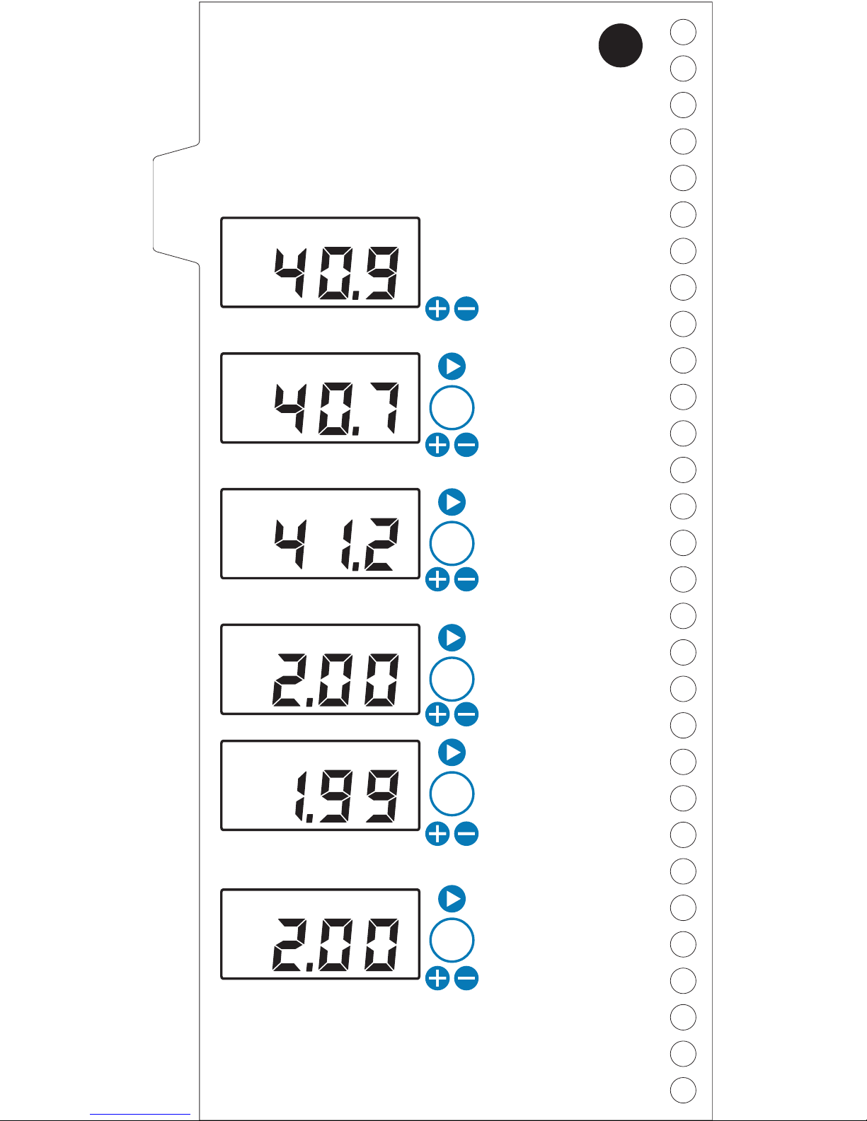
Bus Power
NetMeter continuously monitors the DeviceNet bus
power quality.
Display What it means
Current network bus
voltage is 17.2V.
Minimum bus
voltage recorded
since NetMeter was
plugged in or reset is
17.1V.
Maximum peak-to-
peak (P-P) voltage
recorded since
NetMeter was
plugged in or reset is
0.6V.
Current peak-to-
peak (P-P) voltage
(transient or ripple)
is 0.1Vp-p.
Maximum bus
voltage recorded
since NetMeter was
plugged in or reset is
17.4V.
x1
x4
x3
x2
V
250
V
250
MIN
V
250
MAX
V
250
P-P
V
250
MAX
P-P
What’s a transient?
A transient is a short, temporary deviation of the bus
voltage level.
4
Every DeviceNet network has some level of bus power
transients, which is perfectly acceptable. Transients in
excess of 2V P-P can contribute to node failures and
communication errors in some cases and should be
investigated. Transients in excess of 10V P-P are an
indication of serious network problems..
10
Inhaltsverzeichnis
Beliebte Multimeter Handbücher anderer Marken


Gossen MetraWatt
Gossen MetraWatt METRAmax 6 Bedienungsanleitung

PeakTech
PeakTech 4000 Gebrauchs- und Pflegehandbuch

YOKOGAWA
YOKOGAWA 90050B Bedienungsanleitung

Gossen MetraWatt
Gossen MetraWatt METRALINE DMM16 Bedienungsanleitung

Fluke
Fluke 8846A Bedienungs- und Wartungshandbuch

Tempo Communications
Tempo Communications MM200 Bedienungsanleitung


