Nexus 8 Bedienungsanleitung

CONTENTS
INTRODUCTION 2
Planning the installation 2
Nexus 8 installation example 3
INSTALLATION 4
Nexus 8 system diagram 4
Nexus 8 internal layout 5
Removing the gear tray 5
Mounting the panel / Cable entry 6
Mains connection / battery connection 6
Component wiring
Bell boxes 8
Remote keypads 9
PIR detectors 11
Vibration detectors 12
Door contacts 14
Internal sounders 15
INITIAL POWER-UP 16
PROGRAMMING THE SYSTEM 16
System menus
Engineer menu flow chart 17
Programming zone presets 18
Programming zones 19
Programming system options 20
Event Log Display Guide 21
System Test 22
RESETTING TO FACTORY DEFAULTS 23
GLOSSARY OF TERMS 24
TROUBLE SHOOTING / STOCK CODES 26
TECHNICAL SPECIFICATION 27
ENGINEER NOTES 28
1
© Lynteck Ltd. 1998
INTRODUCTION
We recommended you read this manual before attempting installation in
order to fully utilise the panels functions in your application.
An understanding of the manual will lead to a quicker, easier installation of
the system.
The Nexus 8 has been designed to simplify the installation process, making
wiring easier and subsequently quicker. Individual tampers for each zone
have replaced a single global tamper and each zone now has a 12v auxiliary
power supply. A detachable gear tray aids wiring and protects the printed
circuit board from damage.
PLANNING THE INSTALLATION
• To maximise the system’s effectiveness pre-plan the installation.
• Consider the layout of the building and each of its access points.
• Use the pre-programmed system mode which is best suited to the
building. (See programming guide p.18)
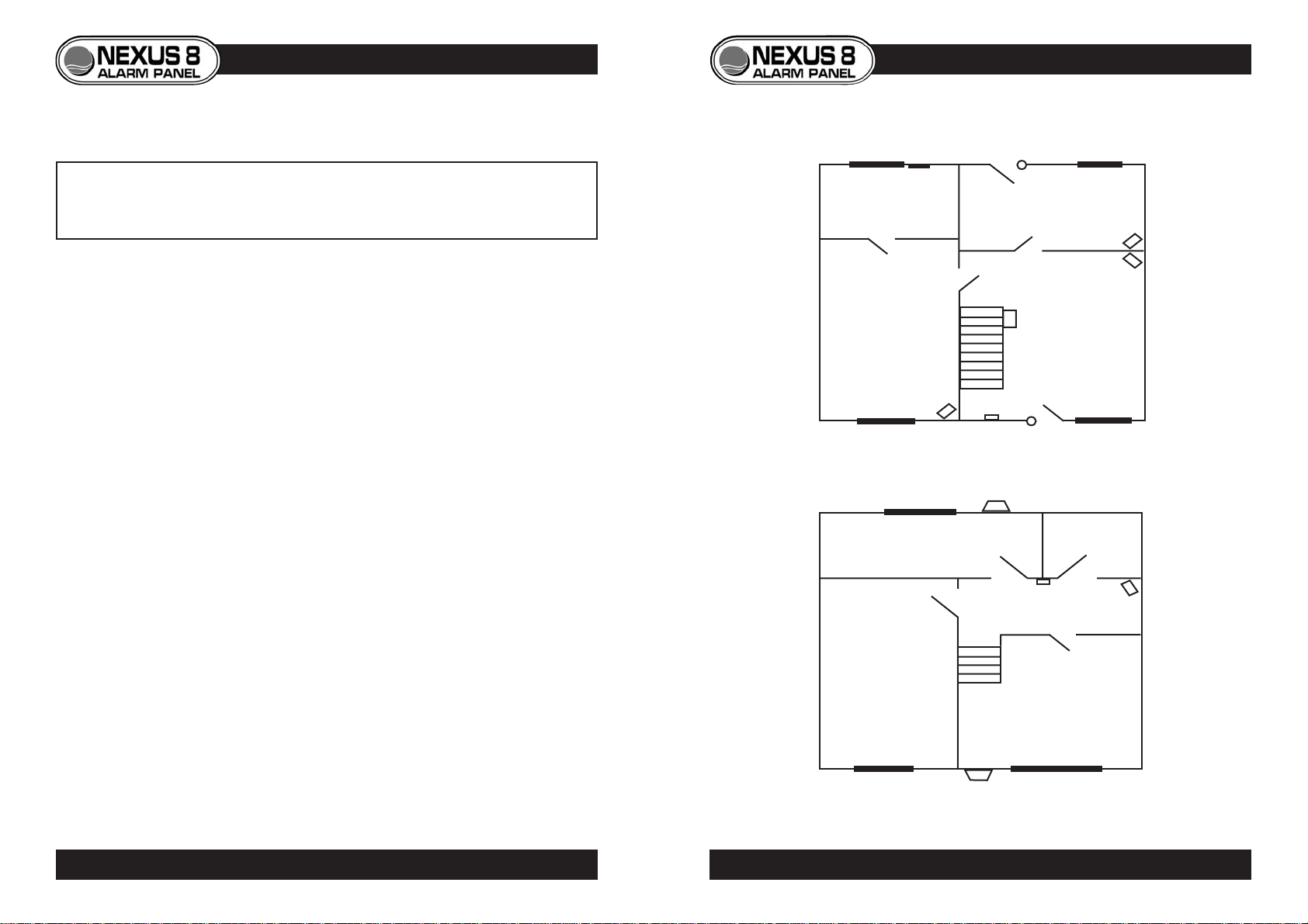
A common layout is shown below, using zone preset option 91 (see
programming guide for details of how to set zone preset options p.18). This
option has been chosen as it best suits the installation, taking layout and user
requirements into account. As the majority of forced entry’s are made through
the front and back doors, they have been fitted with contacts. PIRs have
been fitted guarding against entry through windows, with the exception of
zone 4 which is protected by a vibration detector, making the room suitable
for housing pets. Both zones six and seven are omitted in part sets 1 and 2,
giving access to bedrooms during night setting. The panic attack is located
upstairs close to each of the bedrooms as most burglaries take place at night.
ZONE PRESET OPTION 91 (PANEL DEFAULT)
3
INSTALLATION EXAMPLE
DOOR
CONTACT
DOOR
CONTACT
P.I.R.
P.I.R.
P.I.R. KEYPAD
P.I.R.
VIBRATION
DETECTOR
DUMMY
BELL BOX
PANIC
ATTACK
BELL BOX
CONTROL PANEL
(UNDER STAIRS)
(zone 2)
(zone 3)
(zone 6)
(zone 1)
(zone 8) (zone 7)
(zone 5)
(zone 4)
Ground
Floor
First
Floor
2PLANNING THE INSTALLATION
© Lynteck Ltd. 1998 LY68-030-68

INSTALLATION
System Diagram
CONTROL PANEL INTERNAL LAYOUT
GEAR TRAY REMOVAL
• To release the gear tray,
unscrew and tilt away from
backplate.
• To replace, first place left
side under catches, then tilt
home and replace screw.
5
PANEL LAYOUT • GEAR TRAY REMOVAL
4SYSTEM DIAGRAM
Mains cable
entry
Mains fuse
Mains
connection
terminals Component
connection
terminals
Tamper switch
Auxiliary fuse Bell fuse
Battery
Battery
connection
terminals
Transformer
Battery fuse
6
Mains supply
240v through 3amp
fused spur
Internal
Speaker(s)
Remote
Keypad(s) External
Sounder
/Strobe
Door
Contact(s) PIR
Detector(s) Vibration
Detector(s)
Internal
Battery
Alarm Outputs
8 Detection zones
© Lynteck Ltd. 1998 LY68-030-68

MAINS CONNECTION
• Mains supply is connected
to the panel via a three-way
green terminal block located
on the transformer below
the mains cable entry.
• The supply should come
directly from a consumer
unit through a 3amp fused
spur.
BATTERY CONNECTION
• A sealed lead acid
rechargeable battery must
be connected to the panel
via the two way terminal
block (B+/B-).
• This is situated next to the
battery fuse on the
transformer PCB.
7
Consumer
Unit
3Amp
Spur
BLUE NEUTRAL
GREEN/
YELLOW
BROWN LIVE
N E L
EARTH
PANEL
B+ B-
Battery Fuse
MAINS CONNECTION • BATTERY CONNECTION
MOUNTING THE PANEL
• Use the template on the
rear of the Nexus 8 box to
aid hole marking.
• Drill used should be a size
10 mason bit.
• Plug holes with rawl plugs.
• Use slotted fixing holes to
help level the panel before
fixing it in place with four
1.5”x8 wood screws.
CABLE ENTRY
• 10 individual cable entry’s
are sited beneath the gear
tray.
• Each is individually marked
for ease of cable
identification.
6PANEL MOUNTING • CABLE ENTRY
Cable
Entry's
© Lynteck Ltd. 1998 LY68-030-68

BELL BOXES
• Always consult manufacturers instructions before installation.
• Use 6-core cable (5-cores required).
NEXUS 8 Bell Box Wiring Reference Table
* NOTE - Connect STROBE+ to D
REMOTE KEYPADS
• The Nexus 8 allows up to 4 remote keypads to be used with the system.
• Wiring is via three terminal blocks located at the bottom of the keypad
PCB Cable entry to the keypad is from either top or bottom knockout.
• Use 4-core cable (3-cores required)
+ D -
9
6
66
KEYPAD ZONE 5SPKR
NEXUS 8
PCB
Keypad
terminals
KEYPAD
+ D -
D + - ZONE 5
SPKR
D + -
Keypad 1 Keypad 2
Nexus 8
PCB
Nexus 8
PCB
D + -
4-Core Cable (3-cores used)
4-Core Cable (3-cores used)
KEYPAD WIRING
Single keypad
Two or more keypads
8
Nexus 8 Panel connection HOLD+ HOLD- TPR TRG STR
Suggested wiring colour RED Black WHITE BLUE GREEN
Ventcroft Classic/Spirit H OFF+ H OFF- RTN TRG STB
Texecom Veritas Azura 360 ADCBS
CQR Integra HS +VE 0V RETURN SIREN-TRIG STROBE-TRIG
ADE Sonade*D A T B STROBE -
BELL BOX WIRING
© Lynteck Ltd. 1998 LY68-030-68
BELL/STROBE ZONE 1
TPR HOLD TRG STR
- +
HOLD +
HOLD -
TAMP R
TRG
STR
Lynteck
Bell Box

PIR DETECTORS
• Consult detectors’ instructions before installation.
• If two or more PIRs are connected to a zone, wire power in parallel,
alarm and tamper in series.
• Use 6-core cable.
11
LED
NEXUS 8
PCB
- A A T T +
ZONE 2
ZONE 1
+12v- TAMP RELAY 6-Core Cable
Harrier
PIR
LED
NEXUS 8
PCB
- A A T T +
ZONE 2
ZONE 1
+12v- TAMP RELAY +12v- TAMP RELAY
P.I.R. WIRING
Single PIR
Two or more PIRs
ADDRESSING ADDITIONAL KEYPADS
If two or more keypads are used in an installation, each has to be assigned
an address number in order to communicate with the end-station. This
address number is factory set to 1 and so must be changed on additional
keypads.
To set address number on an additional keypad
• Ensure keypad to be added is not yet powered.
• Remove keypad’s front cover.
• Electrically connect keypad to endstation.
• The keypad will display its address number i.e.
• Press 1 to 4 to change keypads address.
• Press YES to accept and a conformation bleep will be heard.
• Replace keypad cover and test keypad can control the system.
PANIC ATTACK
• The remote keypad also features a
panic attack function.
• Panic attack is operated by
pressing both buttons situated
above the keypad display.
• Panic attack function can be
disabled if required. (See
programming menu p.20)
10 PROGRAMMING ADDITIONAL KEYPADS
6
© Lynteck Ltd. 1998 LY68-030-68

VIBRATION DETECTORS
• If two or more detectors are connected to one zone, power is wired in
parallel, whereas alarm and tamper circuits must be wired in series. • Where 6-cores are used to wire latching detectors, power supply is taken
from tamper circuit. The zones’ + terminal should not be used.
12
NEXUS 8
PCB
- A A T T +
ZONE 3
ZONE 2
T T - + A A 6-Core Cable
NEXUS 8
PCB
- A A T T +
ZONE 3
ZONE 2
T T - + A A
T T - + A A
Lynteck
Vybe
Connection
terminals
VIBRATION DETECTOR WIRING 13
VIBRATION DETECTOR WIRING
NEXUS 8
PCB
Single Non-latching Vibration Detector
Two or more Non-Latching Vibration Detectors
Latching Vibration Detector (7 - Cores)
T T C - + A A T T C - + A A C
BELL/STROBE
LATCH
ZONE 1
Lynteck
Pro-Vybe Lynteck
Pro-Vybe
NEXUS 8
PCB
Latching Vibration Detector (6 - Cores)
T T C - + A A T T C - + A A C
BELL/STROBE
LATCH
ZONE 1
Lynteck
Pro-Vybe Lynteck
Pro-Vybe
- A A T T +
- A A T T +
NOT USED
6-Core Cable
8-Core Cable (7-cores Used)
6-Core Cable
© Lynteck Ltd. 1998 LY68-030-68
ZONE 3
ZONE 2

WIRING INTERNAL SPEAKERS
• A maximum of two 16 ohm or one 8 ohm internal speakers can be wired
to the speaker contacts, power is to be connected in parallel.
15
INTERNAL SPEAKER WIRING
Two Speakers
Single Speaker
KEYPAD
SPKR
S +
KEYPAD
SPKR
S -
+ -
- +
+ -
MAGNETIC DOOR CONTACTS
• If two or more contacts are wired to a zone, alarm and tamper are wired
in series.
NEXUS 8
PCB
- A A T T +
ZONE 1BELL/STROBE
NEXUS 8
PCB
NEXUS 8
PCB
NEXUS 8
PCB
- A A T T +
ZONE 1BELL/STROBE
4-Core Cable
4-Core Cable
14 DOOR CONTACT WIRING
Two or more Door Contacts
Single Door Contact
© Lynteck Ltd. 1998 LY68-030-68

INITIAL POWER UP
• Apply mains power to the system
• This will start the panel in alarm mode and display
• Enter engineer code (7890 - default) to silence alarm
• Re-enter code to reset panel and enter engineer menu
PROGRAMMING THE SYSTEM
System menus
• Master User Menu
• Normal User Menu
• Engineer Menu
The three system menus each give a differing amount of control over the
operation of the panel.
Engineer Menu (flow chart p.17)
•Accessed by entering the engineer code
(7890 - default).
• System can be unset by engineer only if set by engineer.
• Gives access to all master user functions as well as system
programming.
•System programming can only be carried out from
within the engineer menu.
ENGINEER MENU FLOW-CHART
16 17
PROGRAMMING THE PANEL
See USER GUIDE
© Lynteck Ltd. 1998 LY68-030-68

PROGRAMMING GUIDE
19
PROGRAMMING ZONES
18 PROGRAMMING ZONE PRESETS
© Lynteck Ltd. 1998 LY68-030-68
*
* Soak time - 14 days
** Double knock time - 10 seconds.
**
Inhaltsverzeichnis
Beliebte Sicherheitssystem Handbücher anderer Marken


EDM
EDM Solution 6+6 Wireless-AE Bedienungsanleitung

Highway Safety Group
Highway Safety Group EA401 Bedienungsanleitung

Siren
Siren LED GSM Bedienungsanleitung

Detection Systems
Detection Systems 7090i Montageanleitung

Se-Kure Controls
Se-Kure Controls MicroMini SK-4841 Bedienungsanleitung

Siemens
Siemens FDM273 Bedienungsanleitung