Nistune Type#1 Bedienungsanleitung

T
YPE
#1
USB Consult Hardware Installation Manual V3.5
(JECS ECCS 1984-1989 Legacy Engine Control Units,
HITACHI ECCS/NICS 1985-1989 Legacy Engine Control Units)
Copyright 2004 - 2012 Nistune Developments

Nistune Type 1 Hardware Installation Page 2 of 33
I
IN
NT
TR
RO
OD
DU
UC
CT
TI
IO
ON
N
Welcome to Nistune.
The Nistune hardware and software solution provides a means for the car enthusiast to retune
their vehicle whilst retaining their factory ECU and its default programming.
This solution provides many advantages over aftermarket ECUs in that the
•Factory default tuning is maintained once the Nistune board is installed. Upon installation
of the board, vehicle will be operational as usual.
•Additional tuning can then be made against the factory maps for modifications made to the
vehicle. There is no need to tune the car to get it running from scratch, reducing time and
costs of tuning required on dyno.
•There is no need for wiring loom modifications.
Nistune provides realtime tuning and maptracing. It provides the ability to make changes on the fly
to the factory ECU and then the desired results are achieved, save these permanently in non-
volatile memory on the programmable board.
Nistune also provides data logging and playback facilities, the first available for legacy type 1980s
Nissan JECS/Hitachi ECUs. Nistune software also provides a user friendly responsive graphical
interface to perform modifications.
Contained in this manual are the instructions for installing a Nistune board into 1980s Nissan
vehicles.

Nistune Type 1 Hardware Installation Page 3 of 33
WARNING
If your ECU pulses the fuel pump, injectors, fuel regulator, flashes LEDs randomly (or they
just stay on when they shouldn’t) or your engine does not start then your ECU may not
have your board fitted correctly.
Testing has shown on early Nissan ECUs that this can potentially keep the Mass Airflow
Meter heater element on longer than 1 second and blow it like a fuse.
Check:
•Poor connection between the Nistune board and ECU due to failure to secure the
board correctly using hot glue or similar mechanism
•Poor header cable connection to the ECU from Nistune board
•Mismatched Nistune board configuration for the ECU image you are attempting to
use
How to fix this:
•Always firstly try ECU with the factory ROM without the Nistune board to attempt to
start the car properly
•Ensure your Nistune board has the correct base ROM image loaded for your ECU
•Ensure your solder joints are good and header connector is installed correctly
•Attempt USB Consult connection to the Nistune board to verify communication
The Nistune diagnostics document covers problem diagnosis in more detail

Nistune Type 1 Hardware Installation Page 4 of 33
TABLE OF CONTENTS
1. Removing the ECU ....................................................................................................................... 5
2. Opening the ECU .......................................................................................................................... 5
3. Resocketing the ECU.................................................................................................................... 6
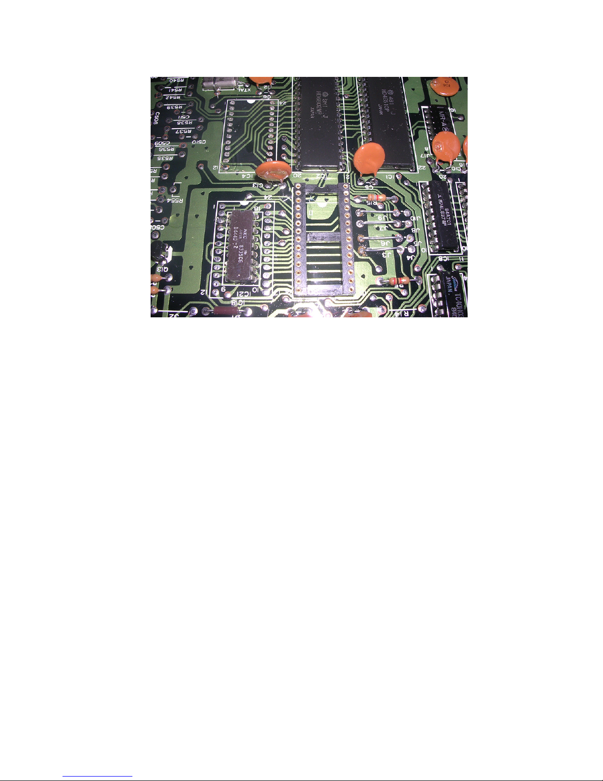
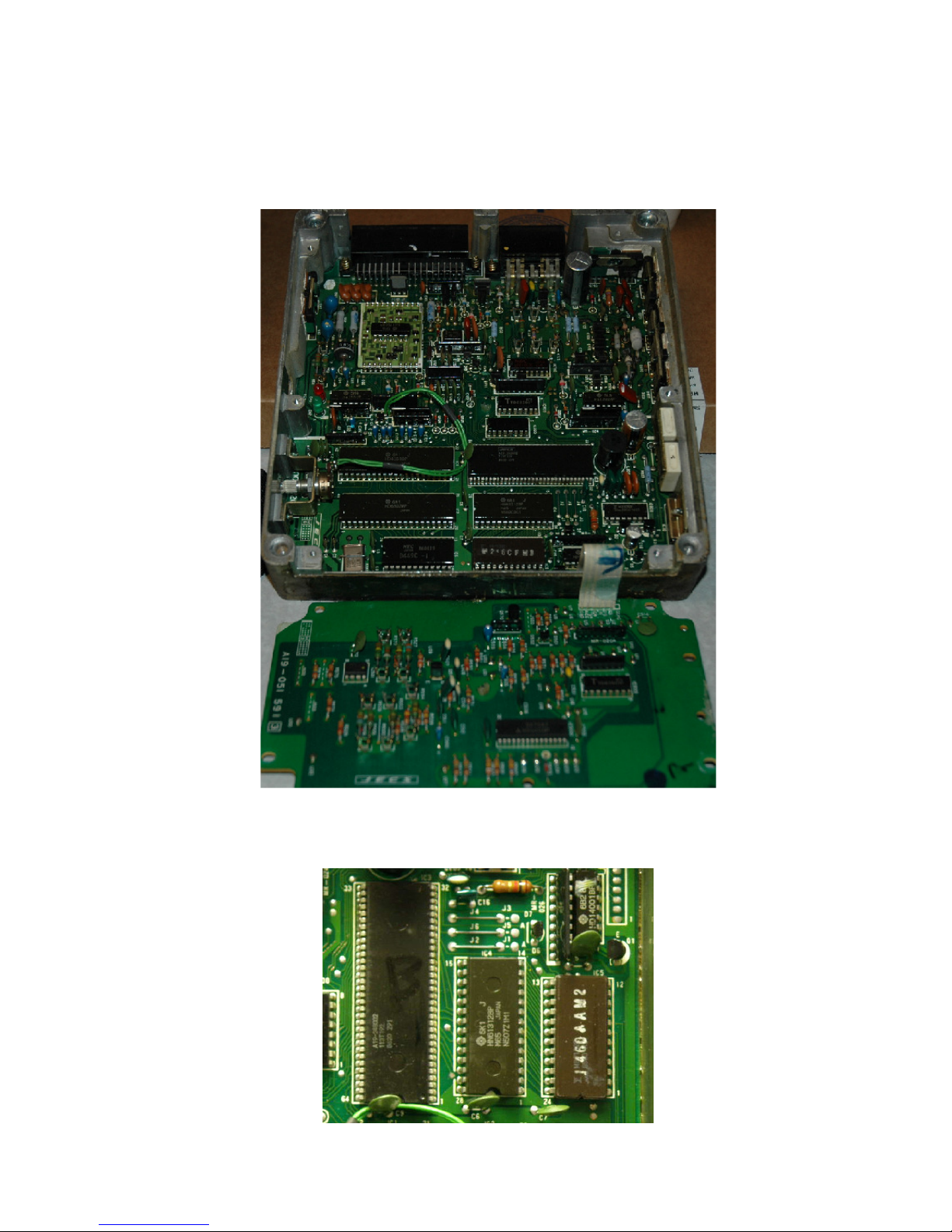
A. 1984-1985 Dual Board - Dual ROM ECUs ................................................................................ 7
B. 1986 Single Board - Dual ROM ECUs..................................................................................... 10
C. 1987 Single Board - Single ROM ECUs .................................................................................. 12
D. 1989 Single Board - Single ROM - Header Connector ECUs .................................................. 13
4. CPU Header Connector Installation (X1) .................................................................................... 16
A. Early Model ECUs ................................................................................................................... 17
B. Later Model ECUs ................................................................................................................... 18
5. USB Connector Installation (X2) ................................................................................................. 22
6. Inserting the Board...................................................................................................................... 24
7. Securing the Board ..................................................................................................................... 26
8. Installing In The Vehicle .............................................................................................................. 27
9. Upgrading ECU MAF hardware................................................................................................... 28

Nistune Type 1 Hardware Installation Page 5 of 33
1. Removing the ECU
Locate the ECU in vehicle to be modified. The location of the factory ECU can be identified from
the vehicle service manual. Usually for most Nissans the ECU is located in the passenger kick
panel. Disconnect your negative battery terminal prior to removing the ECU. Remove the screws
holding in the mounting bracket. Then slide the ECU out from the kick panel and unplug/unscrew
the connectors.
Below is a picture of the ECU with the mounting bracket removed. If sending the ECU away for
Nistune board installation, please send without the mounting bracket.
2. Opening the ECU
For Nistune board installation, firstly remove the top and bottom lids from the ECU. Screws
require a correctly matched Philips head screw driver as they are usually fitted from factory with a
red or blue epoxy which requires some force in order to remove the screws.
The following chapter is split into different sections, dependent on what ECU you have.

Nistune Type 1 Hardware Installation Page 6 of 33
3. Resocketing the ECU
IMPORTANT
Nissan ECUs are sprayed with conformal coating at the end of manufacture. This is to protect
digital circuitry from moisture. Remove conformal coating around the chips to be removed from
the ECU before desoldering.
Use Acetone or paint thinner to remove the coating on both sides of the chips, with a hard bristle
brush and cloth to remove excess coating.
This solution should also be used for removing flux after soldering in the ECU socket and CPU
connector to give the ECU a clean finish after installation
After removing the conformal coating then the chips can be desoldered. Ensure that a suitable
desoldering gun is used and that there is a sufficient heat bridge between each soldered pad and
the desoldering gun. Flux or additional solder can be used to create the heat bridge if reuqired
Read our soldering guide for more information

Nistune Type 1 Hardware Installation Page 7 of 33
A. 1984-1985 Dual Board - Dual ROM ECUs
Vehicles: Early Z31 300ZX and E12 Nissan Exa.
This is a multiboard ECU with a 1K and 8K ROM chip. The two chips need to be removed and
jumpers changed on the board before the Nistune board can be installed.
The ROM images must be read using a special adaptor plugged into an EPROM programmer.
These are then combined into a 16K image and converted into a Nistune ENT file for
programming the board.

Nistune Type 1 Hardware Installation Page 8 of 33
To remove the two ROM chips (U3 and U4) desolder from the top side of the ECU. Be very
careful with the heat of the desoldering gun because the pads on these ECUs lift very easily. It
doesn't take much to break a track on these earlier circuit boards.
Insert the supplied IC socket in IC3 and solder in. Fill in the through holes if IC4 with solder.
Next remove the four brown jumpers. These are J4, J5, J8 and J10. You can shorten these
existing jumpers positions to J3, J6, J7 and J9 by desoldering one end and repositioning it. Be
careful when desoldering the track to ensure that it does not lift. These ECUs are very old and the
circuit boards are fragile.

Nistune Type 1 Hardware Installation Page 9 of 33
The below picture shows the removed ICs, installed 28 pin machine drilled socket and four wire
link jumpers installed in their new locations. Existing brown links can be reused into the new
jumper positions in the ECU.
Next remove R15 which is below J9/J10. This is no longer used with the Nistune board installed.
Note that You will no longer be able to use the factory ROM chip in this ECU once these jumpers
are changed.
Installation of the Nistune board now follows the same procedure as for other 6802 based ECUs
in the following sectionf of this document

Nistune Type 1 Hardware Installation Page 10 of 33
B. 1986 Single Board - Dual ROM ECUs
Vehicles: Z31 300ZX VG30 1986-1987, CR31 / VL / VLT RB30
Note: Some 1986 era ECU have both 28 pin (IC4) and 24 pin (IC5) chips which will need
removing. These chips are located next to each other.
1. Remove both of these ROM chips per picture below. The second smaller ROM is not needed
for normal ECU operation once the Nistune Type 1 board has been installed
Dieses Handbuch passt für folgende Modelle
1
Inhaltsverzeichnis
Andere Nistune Computerhardware Handbücher
Beliebte Computerhardware Handbücher anderer Marken

EMC2
EMC2 VNX Series Betriebsanleitung

Panasonic
Panasonic DV0PM20105 Bedienungsanleitung

Mitsubishi Electric
Mitsubishi Electric Q81BD-J61BT11 Bedienungsanleitung

Gigabyte
Gigabyte B660M DS3H AX DDR4 Bedienungsanleitung

Raidon
Raidon iT2300 Bedienungsanleitung

National Instruments
National Instruments PXI-8186 Bedienungsanleitung


