Nokia 8830 S Bedienungsanleitung

Owner’s Manual
Digital Multimedia
Processor
8830 S


GB 3
DIGITAL MULTIMEDIA PROCESSOR (DMP) 8830
S
Nokia and Nokia Connecting People are registered trademarks of Nokia
Corporation. Other product and company names mentioned herein may be
trademarks or trade names of their owners.
Nokia Multimedia Terminals operates a policy of continuous development.
Therefore we reserve the right to make changes and improvements to any of
the products described in this manual without any prior notice.
The EMC Directive 89/336/EEC is applied to this product.
Copyright © 2000. Nokia Multimedia Terminals.
All rights reserved.
Contents
General Operation of the DMP 4
For your Safety 4
Remote Control 5
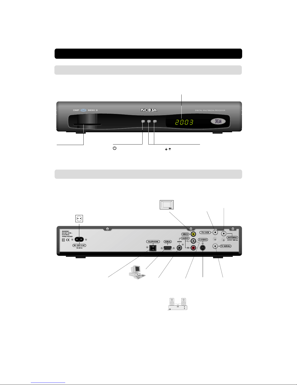
Front and Rear Panel 6
Installation of the DMP 8
Preparing the Remote Control 8
Connecting the DMP to the Dish 8
Connecting the DMP 9
Connecting to the TV 9
Connecting a TV and VCR 9
Connecting to the Telephone Wall Socket 10
Connecting a HiFi System 10
Connecting the AC power cord 10
Tuning Procedure when RF Connections
are Used 11
First time installation 12
General Information 12
The Welcome Menu 12
Channel Search 13
Time Adjustment 13
Viewing Mode 14
General Information 14
Programme Information 14
The “i” (Information) Button 15
Guide 15
List of TV and Radio Channels 16
Options (Green Button) 16
Video Recording 17
The TEXT button 17
Main Menu 18
General Information 18
TV and Radio Channels 18
Edit Channels 18
System Configuration 22
Channel Search 22
TV Settings 23
Time Adjustment 23
Receiver Upgrade 24
Reinstall 24
User Preferences 24
Parental Control 25
Change access code 25
Appearance Preferences 26
System Information 27
Conditional Access 27
Glossary of terms 28
Problem solving 29
Front panel display 30
Technical Specifications 31
Menu Screen Structure 32

GB 4
GENERAL OPERATION OF THE DMP
Throughout this manual you will notice that the everyday opera-
tion of your DMP is based on a series of user friendly on-screen
displays and menus. These menus will help you get the most
from your DMP, guiding you through installation, channel selec-
tion, viewing and many other functions.
All functions can be carried out using the buttons on the remote
control, and some of the functions can also be carried out using
the buttons on the front panel.
If at any time when using the menus (except Installation and
Reinstall) you want to return to the normal TV/Radio mode, press
the EXIT button.
Please be aware that new software may change the functional-
ity of the DMP.
Should you experience any difficulties with the operation of your
DMP, please consult the relevant section of this manual, includ-
ing the Problem Solving, or alternatively call your dealer or a cus-
tomer service adviser.
Please note: The first thing to do before sending the DMP to
service is to:
1: Perform ”Diagnostic” procedure in System Information menu.
2: Try downloading new software into the DMP.
With this procedure, the new software may solve the problem
in the quickest and most efficient way. See the relevant sec-
tion ”Receiver Upgrade” further on in this manual.
•Allow clear space around the DMP for
sufficient ventilation.
•Do not cover the DMP or place it on a
unit that emits heat.
• Use a soft cloth and a mild solution of
washing-up liquid to clean the casing.
• Never allow liquids, spray or other materi-
als to come into contact with the inside of
the DMP.
• Do not connect or modify cables when the
DMP is plugged in.
FOR YOUR SAFETY
• Do not remove the cover.
• Do not allow the unit to be exposed to hot,
cold or humid conditions.
• Service should be carried out only at a Nokia
Authorised Service Centre.
• Please note that the only way to isolate the
DMP completely from the mains supply is
to unplug the mains lead!
• For best protection of your DMP it is
strongly advised that a surge protection
device be installed (not included in standard
accessory package).

GB 5
To switch the DMP in and out of standby mode.
TV To switch between TV or Radio (in viewing mode).
To turn the sound off/on (mute).
- + To adjust the volume of digital programmes.
The DMP’s maximum level is controlled by the TV’s present
volume setting.
0 - 9 To change channel and to select individual menu options.
Note: If 0 is entered as the first digit, the Freeze (on/off) func-
tionality is activated .
Info. To display short and extended information (if transmit-
ted) about current and next programmes.
BACK To go back one level in the menus normally without storing
settings.
EXIT To return to viewing mode from a menu without storing
settings (in menu mode).
MENU To display or exit from the ”Main Menu” screen.
GUIDE To obtain a list of present and following programmes for the
available channels. This information is only shown if your
Service Provider transmits programme information (EPG
information).
P+ P- To change channels up and down by one unit.
To change page in a menu/list/text if more than one page is
available. To browse through teletext history.
▲ ▼ To move up/down in the menus and to change channels.
To change settings in menus.
OK To confirm choices and selection of a highlighted item.
To display the TV/Radio channel list.
(Red) At the moment, no function.
OPTION (Green) To select service options in viewing mode e.g. Al-
ternative Audio DVB Subtitling etc. At the moment, no func-
tion.
(Blue) To toggle between present and previous TV/Radio
channels.
TEXT To enter and exit the application Teletext. At the moment,
no function.
This section describes how to operate the DMP using the buttons on the remote control.
Some of the functions can also be carried out using the buttons on the front panel.
REMOTE CONTROL

GB 6
to put the DMP in and
out of standby mode
to move up/down in
the menus and to
change channels.
Display
shows channel number, error messages, remote con-
trol commands and time in standby mode
Front Panel
Slot
for the Smartcard from the
Service Provider
FRONT AND REAR PANEL
AUDIO L/R
stereo audio
output for TV
or
VIDEO
output for TV
* LNB cable also feeds the
LNB with a supply voltage
of 13/18 V (V/H polarisa-
tion) and a 0/22 kHz signal
(bandswitch).
Max LNB current 400 mA.
S-VIDEO
output for TV
Mains power
socket
95-250 V AC
50-60 Hz
ANTENNA *
Satellite dish in-
put (F-connector)
Rear Panel
SERIAL
serial RS
232 output
TV AERIAL
input for the
terrestrial
VHF/UHF
aerial
(F-connector)
TV/VCR
VHF/UHF out-
put for TV or
VCR
(F-connector)
AUDIO L/R
stereo output for
a HiFi system
MONO
mono audio
output
TELEPHONE
for modem
connection to
the telephone
wall socket

GB 7
How to insert a Smartcard (Nagravision)
•Insert your Smartcard fully into the slot on the front panel of
the DMP. The gold chip should face downwards and in-
wards.
PIN Code
The Smartcard is loaded with a 4-digit code, also called a PIN code
(Personal Identification Number).
The code is essential in order to access future services offered
by the Service Provider.
ABOUT THE SMARTCARD
Note 1!
The gold chip of the
smartcard should face
downwards and inwards
The DMP box has access to scrambled TV/Radio channels based
on the embedded Nagravision system.
To be able to receive these scrambled digital channels you will
need a special Smartcard distributed by your Service Provider or
included in the box. The Service Provider is the programme dis-
tributor of the channels.
Only some “Free-to-Air”channels may be available without the
Smartcard.
After inserting the Smartcard, leave it in the slot permanently.
New and updated information may be downloaded on the
Smartcard from time to time.

GB 8
The box for your DMP should contain the
following items:
•the DMP
•a Remote control with 2 AAA batteries
•an Audio/Video cable(fully featured 1,0 metre)
•an AC power cord
•an Owner’s Manual
•a Software License agreement
INSTALLATION OF THE DMP
About the Audio/Video sockets
•The rear panel of the DMP is equipped with 4 Phono sockets
(see figure on page 6).
•Audio/Video cables are also necessary to get stereo sound
from a stereo TV and video recorder.
AC power
cord
Owner’s manual
License
agrement
Audio/Video
cable
Preparing the Remote Control
•Remove the cover on the battery compartment at the bottom
of the remote control.
•Insert the 2 AAA (1,5 V) batteries, as shown in the diagram,
taking care to observe the +and -markings indicated inside.
•Replace the cover.
Installing the Satellite Dish
•See the ”Fitting instructions for satellite dish”on how to in-
stall the dish.
•Connect the coaxial cable, with F-connectors fitted, from the
LNB on the satellite dish to the socket marked ”ANTENNA”
on the rear panel of the DMP.
Connecting the DMP to the Dish
If you need to fit the F-connectors onto the cable
•Prepare each end of the cable as shown in the diagram. You
will need to fold back the outer braid (as shown).
•Slide the F-connector onto the cable, then turn it clockwise
until it grips the braid.
•Ensure that 3 mm of the core is protruding from the end of the
connector.
8 mm
15 mm
3 mm
F-connector

GB 9
Connecting to the TV
•Connect the Audio/Video cable between the TV and
the AUDIO/VIDEO L R sockets on the DMP.
•Connect an RF cable (not included) from the TV
AERIAL input socket on the TV to the TV/VCR out-
put of the DMP.
•Connect the TV aerial directly to the TV AERIAL in-
put socket on the DMP.
There are many different types of TV/VCR and other equipment
that you can connect to the DMP.
In this manual you will see some of the most common ways to
connect your equipment.
If you use RF leads you will have to tune your TV and VCR to the
DMP output channel (see page 11).
If you have problems with your connections and need help, con-
tact your dealer or Service Provider.
Connecting the DMP
RF
Audio
Connecting a TV and VCR
Refer to your VCR’s manual for full instructions.
If your TV has a Audio/Video socket, but your
VCR does not
•Connect the Audio/Video cable between the TV and
the VIDEO/AUDIO L R sockets on the DMP.
•Connect an RF cable from the RF output on the
VCR to the TV aerial input socket on the TV.
•Connect an RF cable from the RF input socket on
the VCR to the TV/VCR output socket on the DMP.
•Connect the TV aerial directly to the TV AERIAL in-
put socket on the DMP.
DMP
Audio
Video
RF
If your VCR has a Audio/Video socket, but your
TV does not
•Connect the Audio/Video cable between the VCR and
the VIDEO/AUDIO L R sockets on the DMP
•Connect an RF cable from the RF output socket on the
VCR to the TV aerial input socket on the TV.
•Connect an RF cable from the RF input socket on
the VCR to the TV/VCR output socket on the DMP.
•Connect the TV aerial directly to the TV AERIAL in-
put socket on the DMP. DMP
Audio
RF
RF
In
Out
Video
In
Out
In
Out
VCR
RF
VCR
Video

GB 10
Connecting a HiFi System
•Connect an RCA/Cinch stereo cable from the AUDIO L R sock-
ets on the DMP to the LINE, AUX, SPARE or EXTRA input
sockets on your HiFi system.
Note: To avoid interference you must use a screened au-
dio cable.
If your TV has a S-Video socket (S-Video cable is not in-
cluded)
•Connect a S-Video cable from the S-Video socket on the DMP
to the S-Video input socket on your TV.
•Connect an RF cable from the RF output socket on the VCR
to the TV aerial input socket on the TV.
•Connect an RF cable from the TV/VCR output socket on the
DMP to the RF input socket on the VCR.
•Connect the Audio cable between the AUDIO L R sockets on
the DMP and the input sockets on the TV.
•Connect the TV aerial directly to the TV AERIAL input socket
on the DMP. DMP
RF
Connecting the AC power cord
•Connect the AC power cord to the DMP and connect the plug
end to an AC power outlet.
Connecting to the Telephone Wall Socket
You will be offered interactive and Pay-Per-View services from
your Service Provider. You may then need to connect the DMP
to a telephone line.
•To connect the modem cable, plug the cable from the DMP
TELEPHONE socket into the splitter (not included).
•Connect the telephone cable to the splitter and the splitter to
the wall socket.
•For best protection of your DMP it is strongly advised that a
surge protection device is installed (Surge protector not in-
cluded).
In
Out
In
Out
VCR
RF
Audio
S-Video
Inhaltsverzeichnis