OCEM MULTI ELECTRIC LETG Bedienungsanleitung

Document UT-MT-0837_EN Page 1 of 29
Via Farini, 6 – 40124 Bologna - Italy
THI COPY I NOT IGNED BECAU E IT I RECORDED AND DI TRIBUTED VIA THE AUTOMATIC KNOWLEDGE MANAGEMENT Y TEM ( IGNED COPY AVAILABLE AT REQUE T)
THI DOCUMENT I THE PROPERTY OF OCEM; IT CONTENT MAY NOT BE DI CLO ED OR ALTERED WITHOUT THE WRITTEN CON ENT OF OCEM
LED ELEVATED RUNWAY GUARD LIGHT
LETG
OPERATING, IN TALLATION AND
MAINTENANCE IN TRUCTION MANUAL
Drawn up by: E.RAULI Approved by: M.ROMAGNOLI
No. of Attachments: Copy no.:
MULTI
ELECTRIC
group

Document UT-MT-0837_EN Page 2 of 29
Issue 16/10/2015
LETG - LED ELEVATED RUNWAY GUARD LIGHT
EDITIONS
Date
16/10/2015 First Issue
REVISION HISTORY
Rev.
No.
Date Description Author Approved b
LIST OF VALID PAGES
From page 1 to page 29

Document UT-MT-0837_EN Page 3 of 29
Issue 16/10/2015
LETG - LED ELEVATED RUNWAY GUARD LIGHT
TABLE OF CONTENTS
EDITION ........................................................................................................................................... 2
REVI ION HI TORY ............................................................................................................................ 2
LI T OF VALID PAGE ......................................................................................................................... 2
TABLE OF CONTENT ......................................................................................................................... 3
LI T OF FIGURE ................................................................................................................................ 3
LI T OF TABLE .................................................................................................................................. 4
LI T OF ATTACHMENT ..................................................................................................................... 4
PRODUCT WARRANTY TERM AND CONDITION ............................................................................. 5
AFETY INFORMATION ...................................................................................................................... 5
1
GENERAL INFORMATION ................................................................................................. 7
2
KEY FEATURES ................................................................................................................. 7
2.1
Description of LETG light fixture .................................................................................... 7
2.2
Input power .................................................................................................................... 7
2.3
Operating conditions ...................................................................................................... 8
3
FIXTURE TYPE IDENTIFICATION ...................................................................................... 17
4
INSTALLATION .............................................................................................................. 18
5
AZIMUTH AND ZENITH ANGLE ADJUSTMENT ................................................................. 19
6
MAINTENANCE ............................................................................................................. 21
6.1
Periodic checks ............................................................................................................. 21
6.2
Non-scheduled maintenance ....................................................................................... 22
6.3
REPLACEMENT .............................................................................................................. 22
6.3.1
Replacing lens and gasket ................................................................................... 22
6.3.2
Replacing the LED board ..................................................................................... 22
6.3.3
Replacing the power supply board (power supply board assembly) ................. 22
6.3.4
Replacing the power supply cable with connector............................................. 23
7
TROUBLESHOOTING ...................................................................................................... 24
8
WIRING DIAGRAMS ....................................................................................................... 25
LIST OF FIGURES
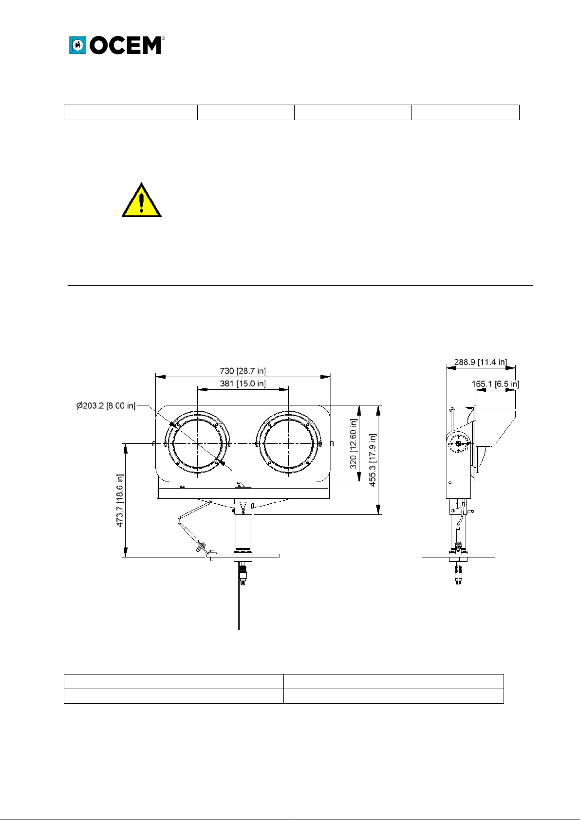
Figure 1 - Overall dimensions ............................................................................................................ 8
Figure 2 - P/N explanation............................................................................................................... 17
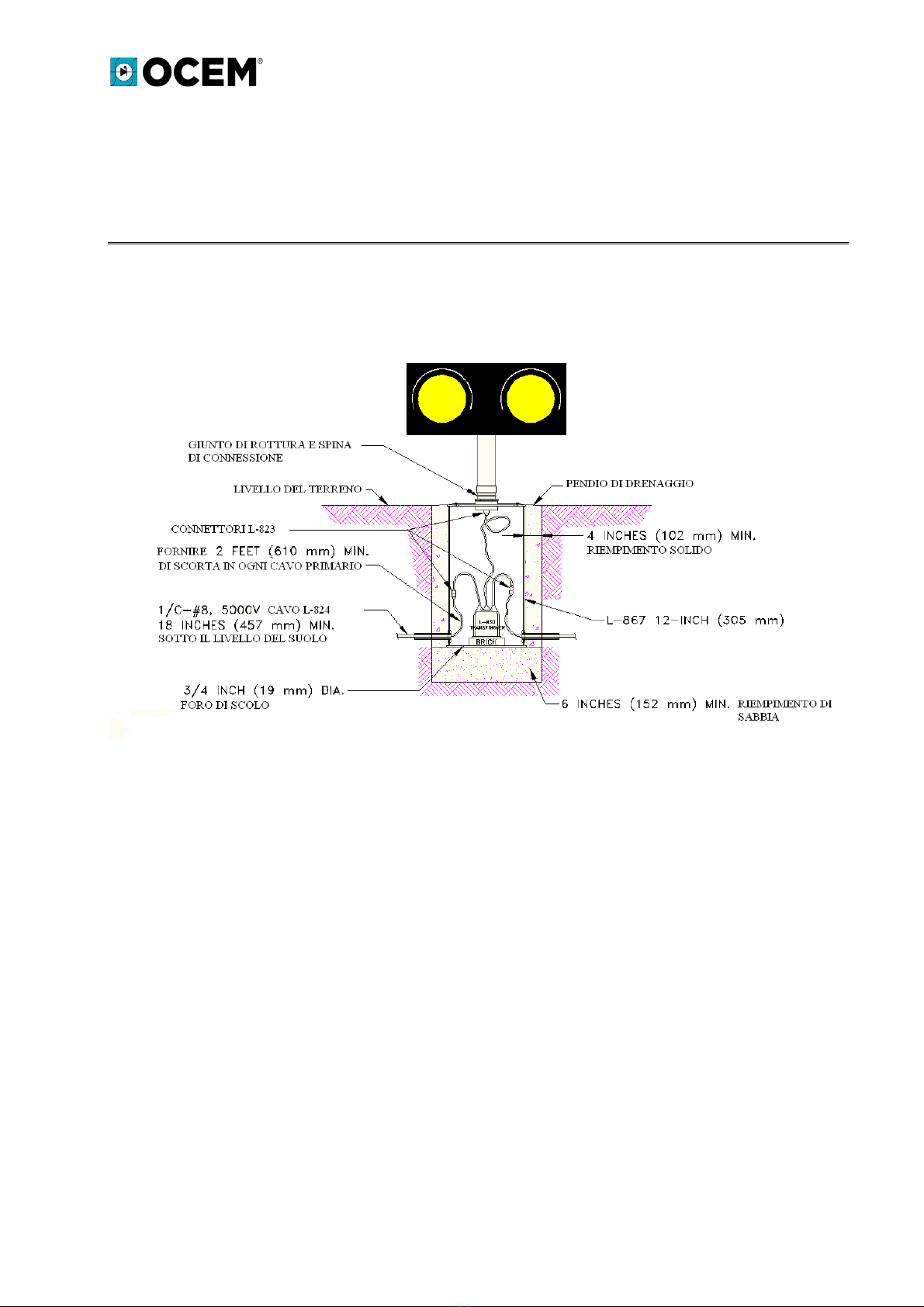
Figure 3 - Installation on FAA L-867 base plate and base plate ...................................................... 18
Figure 4 - Horizontal and vertical aiming indexes ........................................................................... 20
Figure 5 - eries power supply unit housing ................................................................................... 23
Figure 6 - Housing of parallel power supply unit with dusk sensor ................................................ 23

Document UT-MT-0837_EN Page 4 of 29
Issue 16/10/2015
LETG - LED ELEVATED RUNWAY GUARD LIGHT
Figure 7– Non-monitored series circuit power supply.................................................................... 25
Figure 8– Non-monitored series circuit power supply with switch ................................................ 25
Figure 9– Monitored series circuit power supply ........................................................................... 26
Figure 10– Monitored series circuit power supply with switch ...................................................... 26
Figure 11– Non-monitored parallel circuit power supply with or without photocell .................... 27
Figure 12– Non-monitored parallel circuit power supply with switch, with or without photocell 27
Figure 13– Monitored parallel circuit power supply with or without photocell ............................ 28
Figure 14– Monitored parallel circuit power supply with switch, with or without photocell ........ 28
Figure 15 – Wiring diagram for connection of monitored LETG to transformer. ........................... 29
LIST OF TABLES
Table 1 - Consumption ...................................................................................................................... 8
Table 2 - Weight and Volume of LETG............................................................................................... 8
Table 3 -Periodic checks .................................................................................................................. 21
Table 4 - Troubleshooting ............................................................................................................... 24
LIST OF ATTACHMENTS

Document UT-MT-0837_EN Page 5 of 29
Issue 16/10/2015
LETG - LED ELEVATED RUNWAY GUARD LIGHT
PRODUCT WARRANTY TERMS AND CONDITIONS
THI WARRANTY I THE OLE WARRANTY MADE BY THE MANUFACTURER AND REPLACE ANY OTHER
WARRANTIE , EXPRE , IMPLIED OR TATUTORY, INCLUDING, BUT NOT BY WAY OF LIMITATION, ANY
WARRANTIE OF MERCHANTABILITY OR FITNE FOR A PARTICULAR PURPO E.
OCEM - ENERGY TECHNOLOGY warrants to the direct purchaser of the products manufactured by the
Company that such products are free from defects in material at the time of delivery to the Purchaser,
provided that no warranty is made with respect to:
(a) any products that, in the Company's judgement, have been repaired or modified in such a manner as
to damage them;
(b) any products that, in the Company's judgement, have been exposed to negligence or adverse
conditions or stored improperly;
(c) any products that were not operated or serviced in accordance with normal practice and with the
recommendations and specifications issued by the Company;
(d) broken warranty seals, if any, will immediately void the warranty.
The Manufacturer's obligations under this warranty are limited to using reasonable efforts to repair, or
alternatively, replace during regular working hours those products that in the Manufacturer's judgement
proved not be as warranted within the applicable warranty period.
All costs of transportation of any claimed, repaired or replaced products to or from the Company's facility
shall be borne by the Purchaser.
The Company may demand that the claimed product be delivered to its facility at the Purchaser's expense
in order to establish whether the claim is covered by warranty.
The installation costs for a repaired or replacement product shall be borne by the Purchaser. Replacement
parts provided under this warranty are covered for the remainder of the warranty period as if they were
original equipment parts. This warranty does not cover downtime; the Company disclaims all liabilities for
damages caused by any delays in connection with warranty service.
PLEASE READ THIS DOCUMENT CAREFULLY
Please read the entire document carefully before installing, commissioning, operating, servicing or
disposing of the equipment.
SAFETY INFORMATION
Use great care when working with this equipment. It is normally used in connection with or connected to
circuits operating at dangerous voltage levels and can be fatal.
The following section contains important information on the safety rules that must be observed when
installing and operating the equipment.
Improper use of the equipment or lack of care in applying the safety procedures and instructions provided
in this document may create a hazard. Avoid contact with voltage or current sources.
Do not remove the protections or safety devices for any reason whatsoever.

Document UT-MT-0837_EN Page 6 of 29
Issue 16/10/2015
LETG - LED ELEVATED RUNWAY GUARD LIGHT
SERVICING THE EQUIPMENT - SKILLS
ervicing and access to the internal parts of the equipment shall be done by qualified, properly trained
personnel aware of the risks associated with electricity and high voltage.
Follow the safety rules when using the equipment or cables and other apparatus connected to it.
DO NOT WORK ON LIVE CIRCUITS
Do not work on the converter or any apparatus connected to it when the circuits are live.
WHEN USING AND MAINTAINING THE EQUIPMENT, OBSERVE THE PRECAUTIONS FOR HIGH VOLTAGE
Before each access, inspection or operation, ensure that the equipment has been switched off by opening
the main switch and removing power to the units (open power switch upstream of line).
Wait until discharge time has elapsed (at least 5 minutes) and check for voltage before accessing the
equipment.
RESUSCITATION
Maintenance personnel must be aware of the risks connected with electricity and the criteria for the
prevention of electrical shock hazards and should be familiar with resuscitation techniques.
CE MARK
This equip
ment complies with the requirements of European regulations on CE marking. User
must observe all instructions provided in this document.
This equipment complies with the requirements of EEC Directives 2004/108/EEC and
2006/95/EEC concerning “Electromagnetic Compatibility” and “Low Voltage Electrical
Equipment”, respectively
TAKING THE EQUIPMENT OUT OF SERVICE
In the event of scrapping, dismantling, destruction or disposal, user must observe all necessary
precautions for the components and materials to be disposed of, in accordance with local regulations and
applicable law in force.

Document UT-MT-0837_EN Page 7 of 29
Issue 16/10/2015
LETG - LED ELEVATED RUNWAY GUARD LIGHT
1GENERAL INFORMATION
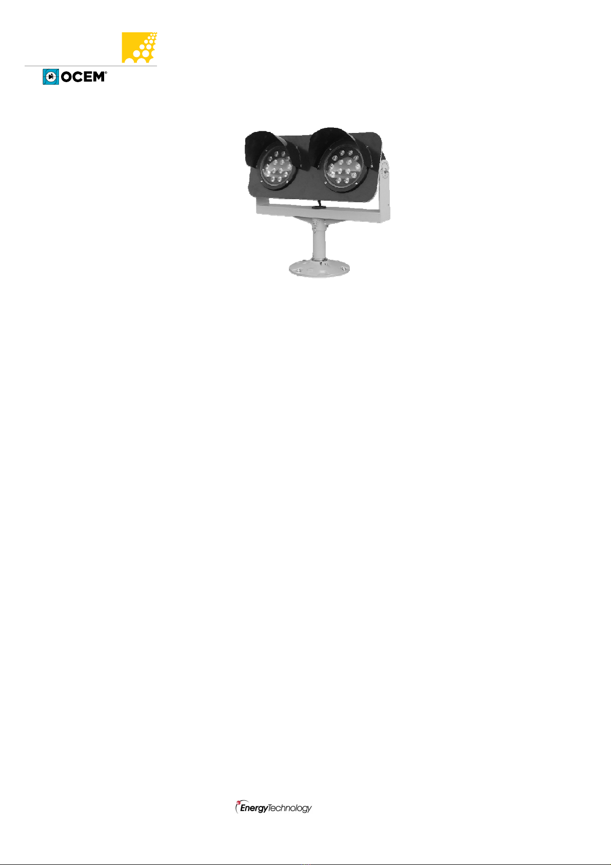
LETG is an LED Elevated Runway Guard Light with two yellow lights that flash alternately. It is
used to warn pilots or ground vehicle operators that they are approaching the runway.
LETG is in compliance with
•ICAO –Annex 14, Vol.I, ect.5.3.22 Configuration A, high intensity
•FAA – AC 150/5345-46 (Current Edition) and Engineering Brief No.67, meets the
requirements outlined in AC 150/5340-30
•EASA – C -ADR-D N Book 1 Fig.U-28
•IEC – T 61827
•NATO – TANAG 3316
•CAA – CAP 168
•IAAE – TP 312
•ENAC – Regulation on airport construction and operations of the Italian Civil Aviation
Authority
2KEY FEATURES
2.1 Description of LETG light fixture
The fixture consists of:
•Two unidirectional yellow LED light sources spaced 381 mm (15”) apart. The two light
sources flash alternatively at a rate of 45-50 times per minute.
•Aluminium housing accommodates LED boards and power supply unit.
•U-shaped aluminium support frame with zenith and azimuth angle adjustment marks.
Zenith angle can be adjusted in a 0° to 20° range in 1° increments. Azimuth angle can be
adjusted in a -20° to +20° range in 5° increments.
•Mounting leg with frangible groove and 2”-11 ½ NPT male threading
•L-823 power connector, 2-pin without monitoring or 5-pin with monitoring.
•Use a control and monitoring device capable of detecting a single burnt-out lamp (MCC )
•The fixture will be installed on a high-strength steel base plate with
2”-11 ½ NP M threading
2.2 Input power
Two versions are available with the following characteristics:
•powered by 2.8 A6.6A series circuit (FAA Mode 1)
•voltage driven 120Vac-240Vac (FAA Mode 2)
MODE CONSUMPTION TRANSFORMER CCR
1. eries circuit 32VA 45W 65VA
2. 120V parallel circuit 32VA - -

Document UT-MT-0837_EN Page 8 of 29
Issue 16/10/2015
LETG - LED ELEVATED RUNWAY GUARD LIGHT
2. 240V parallel circuit 32VA - -
Table 1 - Con umption
NOTE: Electrical characteristics have been determined using
current regulators and insulation transformers manufactured
and/or marketed b OCEM. These data ma var when third-
part current regulators and transformers are used.
2.3 Operating conditions
•Operating temperature -40°C to +55°C (-40°F to +131°F)
•Humidity: 0 to 100%
•Wind velocity: 480 km/h (300mph)
Figure 1 - Overall dimen ion
WEIGHT OUTER PACKING
18kg 80x50x35 cm
Table 2 - Weight and Volume of LETG

Document UT-MT-0837_EN Page 17 of 29
Issue 16/10/2015
LETG - LED ELEVATED RUNWAY GUARD LIGHT
3FIXTURE TYPE IDENTIFICATION
LETG – I – S– M – 0–0 - T
Basic P/N
Conformit
IY = ICAO Yellow
FY = FAA Yellow
TR = Traffic Red
Mode of operation
= eries Power Circuit
D= 100V to 240V Parallel Power Circuit
Monitoring
0= Non-monitored
M= Monitored
Photocell (mode of operation D onl )
F= With Photocell
0=No Photocell
Power disconnection:
C = ON/OFF witch
0= No ON/OFF witch
Options
T = afety Rod (standard on FY version)
Figure 2 - P/N explanation

Document UT-MT-0837_EN Page 18 of 29
Issue 16/10/2015
LETG - LED ELEVATED RUNWAY GUARD LIGHT
4INSTALLATION
The fixture is normally installed on level ground, at the edges of the runway, on a 12” FAA L-867
base, that will be used to house the transformer, and a base plate. Please refer to FAA
instructions provided in AC 150/5340-30 and ICAO Annex 14, vol. I.
Figure 3 - In tallation on FAA L-867 ba e plate and ba e plate
Assuming that the L-867 base has been correctly installed, install fixture and base plate (fig.3) as
follows:
•Thread the fixture connector through U-shaped frame, frangible coupling and locking ring;
ensure to screw the locking ring all the way up to the edge of frangible coupling thread.
•Connect fixture connector to the receptacle in the top section of the base plate
•crew the frangible coupling onto the threaded section of the base plate. Apply anti-seize
grease first and do not tighten yet.
•Orient the row of holes in the frangible coupling in the same direction as the light beam
(horizontally) and tighten the locking ring fully onto the base plate.
•Insert the fixture with the U-shaped frame on the frangible coupling and insert the
alignment pin through the holes. Do not tighten the two rear retaining screws of the U-
shaped support frame.
•Orient the fixture (see section 5).
Inhaltsverzeichnis
Andere OCEM Beleuchtungsausrüstung Handbücher

OCEM
OCEM Multi Electric LRTH04 Gebrauchsanweisung

OCEM
OCEM LIRE Series Gebrauchsanweisung

OCEM
OCEM LHE Gebrauchsanweisung

OCEM
OCEM LHI Gebrauchsanweisung

OCEM
OCEM PAPI Bedienungsanleitung

OCEM
OCEM LIMS Gebrauchsanweisung

OCEM
OCEM MULTI ELECTRIC LTHE04 Gebrauchsanweisung

OCEM
OCEM LSDS Gebrauchsanweisung

OCEM
OCEM FP150 Gebrauchsanweisung

OCEM
OCEM SLTH Gebrauchsanweisung
Beliebte Beleuchtungsausrüstung Handbücher anderer Marken

Qazqa
Qazqa Suplux SL 3 Black 103062 Bedienungsanleitung

Commercial Electric
Commercial Electric 54568141 Bedienungsanleitung

CREE LIGHTING
CREE LIGHTING 304 Series Bedienungsanleitung

Goobay
Goobay 49867 Bedienungsanleitung

ECOMAN ITALIA
ECOMAN ITALIA LED T8 Bedienungsanleitung

Alkalite
Alkalite Krypton KT-81 Bedienungsanleitung