Olympus U-5RES-ESD Bedienungsanleitung

INSTRUCTIONS
CODED FUNCTION SYSTEM
This instruction manual is for the Olympus Coded Function System. To ensure the safety, obtain optimum
performance and to familiarize yourself fully with the use of this system, we recommend that you
study this manual and the manuals of units used in combination with this system thoroughly before
operating the system.
Retain this instruction manual in an easily accessible place near the work desk for future reference.
U-5RES-ESD
U-D5BDRES-ESD
U-D7RES
BX3-RFAS
U-HSEXP
U-CBS
A X 7 8 7 7
This device complies with the requirements of both directive 2004/108/EC concerning
electromagnetic compatibility and directive 2006/95/EC concerning low voltage. The CE marking
indicates compliance with the above directives.
In accordance with European Directive 2002/96/EC on Waste Electrical and Electronic Equipment,
this symbol indicates that the product must not be disposed of as unsorted municipal waste, but
should be collected separately.
Refer to your local Olympus distributor in EU for return and/or collection systems available in your
country.

IMPORTANT — Be sure to read this section for safe use of the equipment. — 1,2
1 CONNECTOR NOMENCLATURE 3
2 SYSTEM CHART 4,5
3 CABLE DISTRIBUTIONS 6-9
4 READOUT/EXTERNAL TRANSMISSION OF CODED INFORMATION 10
Page
CONTENTS
1BX43 (System with LED Lamp Housing)............................................................................................................................................................... 7
2BX43 (System with Halogen Lamp Socket)...................................................................................................................................................... 8
3BX53 System................................................................................................................................................................................................................................................. 9
CODED FUNCTION SYSTEM
* When using Industrial Microscope Frames such as BX41M-LED, BX51/51M, GX51/71 or STM6, refer to manual
“U-5RES-ESD/U-D5BDRES-ESD” for detailed installation instructions.

1
IMPORTANT
SAFETY PRECAUTIONS
This system enables to read coded information from the Coded Fluorescence Illuminator (BX3-RFAS) and
the Coded Revolving Nosepiece (U-D7RES, U-5RES-ESD, U-D5BD5RES-ESD), and to transmit the information
externally. To ensure the safety, refer to this manual and the manuals of units used in combination with
this system thoroughly before operating the system.
1. Before connecting the cables, make sure that the POWER switch of the U-CBS control box is set to OFF (out position).
2. For safety, always use the provided AC adapter to power the system.
3. Keep the cables away from the lamp housing and the surroundings. Otherwise, the cables may melt and cause an electric
shock hazard.
4. Application of excessive force to the cables such as by pulling may cause damage. So never apply such force to the
cables.
Safety Symbol
The following symbol is found on the system. Study the meaning of the symbol and always use the equipment in the
safest possible manner.
Symbol Explanation
Indicates a non-specific general hazard. Follow the description given after this symbol or in
instruction manual.
Indicates that the main switch is ON.
Indicates that the main switch is OFF.

2
CODED FUNCTION SYSTEM
1Getting Ready
2Caution
1. This system is composed of precision instruments. Handle it with care and connect cables gently to avoid subjecting it
to sudden or severe impact. Besides, this system is not waterproof.
2. Do not use the system where it is subjected to direct sunlight, high temperature and humidity, dust or vibrations.
3. To avoid malfunction, never connect or disconnect a cable while the POWER switch of the control box is set to ON
(depressed position). Otherwise, malfunction may result.
4. To avoid malfunction, never attempt to open, disassemble or modify any part of the system.
5. Before disposing of this product, be sure to follow the regulations and rules of your local government.
If the system is used in a manner not specified by this manual, the safety of the user may be imperiled. In addition, the
system equipment may also be damaged. Always use the system as outlined in this instruction manual.
The following symbols are used to set off text in this instruction manual.
: Indicates a potentially hazardous situation which, if not avoided, may result in minor
or moderate injury or damage to the equipment or other property. It may also be used
to alert against unsafe practices.
} : Indicates commentary (for ease of operation and maintenance).
CAUTION

3
1
1CONNECTOR NOMENCLATURE
Control Box for Coded Function
U-CBS
U-D7RES
U-5RES-ESD
U-D5BDRES-ESD connector
BX3-RFAS connector
POWER switch
ON: Depressed position.
OFF: Out position.
Microscope frame hangers (top/bottom)
RS-232C connector
Option connector
The U-CBM can be connected.
U-HSEXP connector
For the external DP21 exposure button.
AC adapter input connector
4
CODED FUNCTION SYSTEM
2
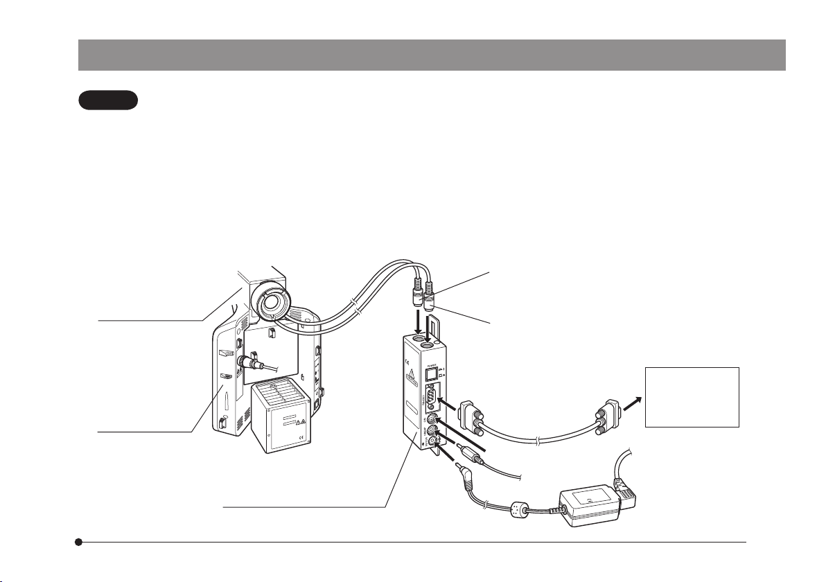
2SYSTEM CHART
· Entrust the assembly and adjustments of the modules marked*to Olympus.
The connectors of the U-CBS are sealed with dust covers. Remove the dust covers only from the connectors
you want to connect cables.
· Be sure to connect the module designated by Olympus to each connector. If a non-designated module is
connected, the performance of the entire system cannot be guaranteed.
· Before connecting the cables, make sure that the POWER switch of the U-CBS control box is set to OFF (out
position).
Hold each connector in the appropriate orientation and insert it all the way into the connector. If a connector
is provided with clamping screws, be sure to tighten them.
· Do not insert a non-designated connector. Otherwise, the connector may be damaged.
CAUTION
Coded Fluorescence
Illuminator *
BX3-RFAS
Microscope Frame
BX43F
BX53F
Control Box for Coded Units Note 3)
U-CBS
U-D7RES Note 2)
U-5RES-ESD
U-D5BDRES-ESD connector
BX3-RFAS connector *Note 2)
· PC
· DP21Note 4)
(Microscope
Digital Camera)
RS-232C cable Note 1)
Option connector
AC adapter
U-HSEXP connector

5
Fig. 2
Fig. 1
Note 1)
RS-232C cable specifications
D-sub 9-pin (female) D-sub 9-pin (female)
Note 2)
When connecting a cable to the BX3-RFAS, U-D7RES, U-5RES-ESD or
U-D5BDRES-ESD connector, align the tmarkings @ on the connectors
of the cable and the U-CBS (Fig. 1).
Note 3)
Hang the U-CBS control box 2on the hangers 3on the rear of the
microscope frame (Fig. 2).
}When using coded revolving nosepiece (U-5RES-ESD, U-D5BDRES-ESD),
place U-CBS on the table. Refer to manual of coded revolving nosepiece.
Note 4)
When this system is used with the DP21 microscope digital camera, set
the power switches to ON in the order of: @ U-CBS and 2DP21-CB.
Otherwise, the DP21 will not recognize the U-CBS. Also if the U-D7RES,
U-5RES-ESD or U-D5BDRES-ESD are not connected to the U-CBS, the
DP21 will not recognize it either. So be careful.
1
3
2

6
CODED FUNCTION SYSTEM
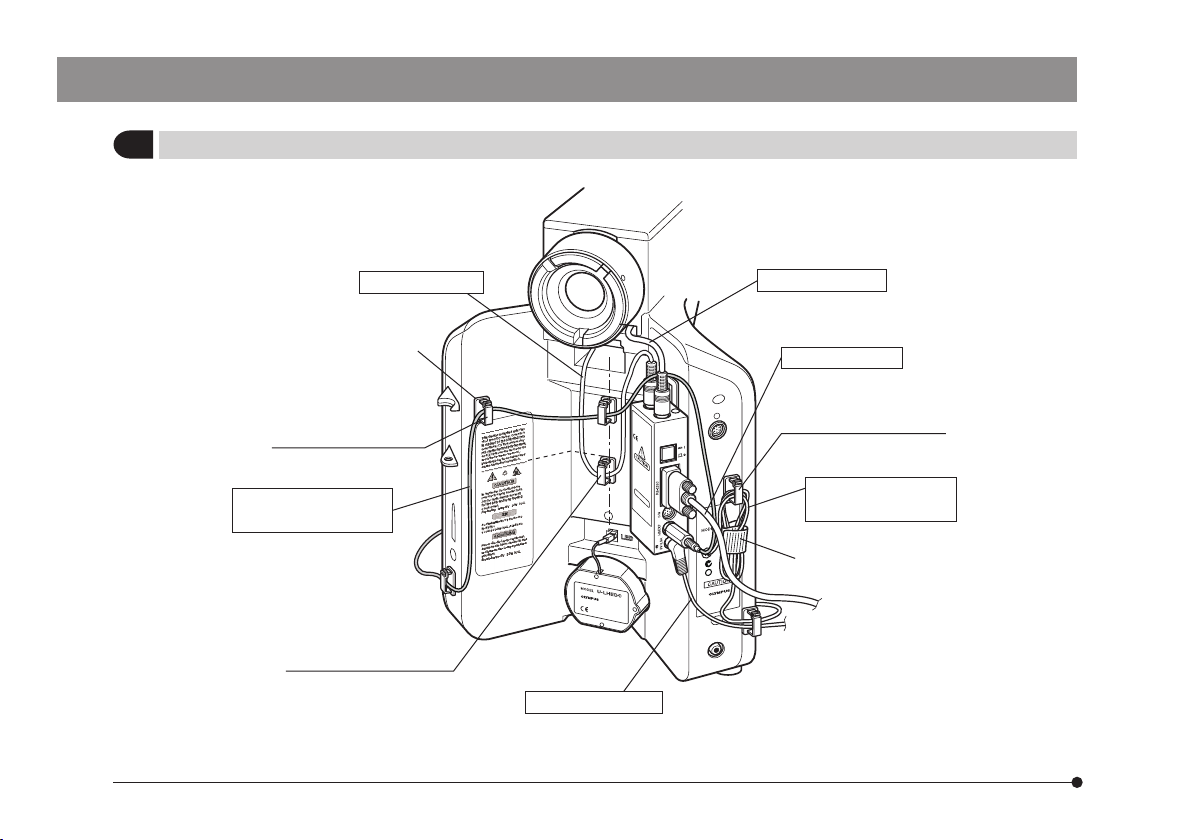
3
3CABLE DISTRIBUTIONS
}The cables can be laid properly by attaching the cable holders provided with each module on the rear panel of the
microscope frame.
U-CBS control box .......... x6
U-D7RES coded revolving nosepiece .......... x2
U-5RES-ESD coded revolving nosepiece .......... x4
U-D5BDRES-ESD coded revolving nosepiece .......... x4
U-LS30AD adapter .......... x1
· In the subsequent pages, the positions for attaching the cable holders and the method of cable distribution will be
described for each microscope system.
· The number of the cable holders used vary depending on the modules used in the system.
· If the cable holders are attached in widely deviated positions, the cable may become unable to reach the connector. Be
sure to attach the cable holders while confirming that their positions allow the cable to reach the connector
· Be sure to remove cable slacks before closing the cable holders.
POWER
7
1BX43 (System with LED Lamp Housing U-LHLEDC)
Use 6 cable holders.
Align with the top left
corner of the label.
Align with the height of
line drawn on the label.
Align with the top right
corner of the label.
Banding band
(Provided with U-HSEXP)
*Only either cable should be used.
U-D7RES cable BX3-RFAS cable
RS-232C cable
AC adapter cable
U-HSEXP cable for
right side installation
*U-HSEXP cable for
left side installation
*
Dieses Handbuch passt für folgende Modelle
5
Inhaltsverzeichnis
Andere Olympus Multifunktionsdrucker Handbücher

Beliebte Multifunktionsdrucker Handbücher anderer Marken

Triumph Adler
Triumph Adler DC 2016 Handbuch

Epson
Epson WorkForce WF-2510 Benutzerhandbuch

Epson
Epson Stylus Scan 2000 Installations- und Betriebshandbuch

Epson
Epson PictureMate Snap PM 240 Bedienungsanleitung

Konica Minolta
Konica Minolta bizhub C35 Bedienungsanleitung

Brother
Brother MFC-J430w Bedienungsanleitung


