Opt Lasers PLH3D-CNC Adapter Bedienungsanleitung

1
PLH3D-CNC Adapter
Table of Contents
Introduction 2
Controls and Indicators 5
Application 6
PLH3D-CNC Adapter Settings 9
Connection to CNC Machines 10
X-Carve 10
Stepcraft 10
Shapeoko 11
Zmorph 12
Workbee 13
Smooth Stepper 14
BlackBox Motion Control System 14
Miscellaneous 15
For Advanced Users 16
Troubleshooting 20

2
Introduction
PLH3D-CNC Adapter (center), PLH3D-6W-XF (bottom left), optional cables with CNC machine connector (bottom right),
keylock (top right) and stop button (top left).
The PLH3D-CNC Adapter serves as a versatile interface and safety unit connected between a CNC machine and a
high-performance PLH3D laser head.
Many types of CNC machines and 3D printers with different control voltage standards and levels available on the
market may be used to control the PLH3D head. The PLH3D-CNC Adapter converts all these signals to the standard
compatible with the PLH3D head. The PLH3D-CNC Adapter contains widely-used, industry-standard screw connectors. A
dedicated, low-noise desktop power supply unit assures compatibility and reliability as well as eliminates problems caused
by using third-party power supplies. The general status (power on, arming, laser working) may be checked at a glance by
looking at the three LEDs.
The laser head may be checked by generating a short laser pulse at maximum power.
The key function of the PLH3D-CNC Adapter is to “arm” and “disarm” the laser head. Arming means turning the
head power supply on; the armed head is then able to generate laser beam. Disarming (turning the head power supply off)
brings the laser head in a safe state where generating a laser beam is fully impossible.
Built-in safety mechanisms prevent misuse and unexpected behavior in case of an emergency. The key switch
protects the laser head from being armed by children and other unauthorized persons. Arming the laser head is always done
manually by the user, by pressing a button. Special circuitry prevents arming during an internal electrical malfunction. The
laser head is automatically disarmed in case of an emergency: loss of the mains supply (grid power), PSU failure, breakage
or disconnection of the laser head cable. After disarming, the system remains in a safe state and rearming always requires
the user to press the button.
Additional safety mechanisms can be incorporated into the system by adding up to two external switches (e.g. limit
switch, key switch, or e-stop). There is also an additional extension connector for future needs.

3
Key features of the PLH3D-CNC Adapter:
●Keylock for preventing use by unauthorized personnel
●Safe start
●Laser pulse test
●Stop button used also to arm, test, and set mode
●Status LEDs- power, armed, laser and setting of enable modes
●Connectors: PLH3D laser head, control, extensions, and external switches
●Power connector
●External desktop low-noise power supply
●Machined aluminum quality enclosure
●Optional PLH3D laser cables and signal cables dedicated to a CNC machine or controller type
●Optional external key lock, stop button, and sensors
●Compatible with PLH3D laser heads
●Can be configured for matching with most of CNC machines and 3D printers

4
Overview
1
Laser head terminal block
2
External Switch terminal block
3
Extensions connector
4
Power supply connector
5
Control terminal block
6
Mode button
7
LED status indicators
8
Key switch

5
Controls and Indicators
1. LASER HEAD TERMINAL BLOCK
Attach the laser head cable here.
2. EXTERNAL SWITCH TERMINAL BLOCK
Up to two external switches (e.g. limit switch, key switch, e-stop) that arm/disarm the laser head can be connected
to the PLH3D-CNC Adapter. When not using a switch, replace it with a jumper wire.
Opening any external switch disarms the laser head immediately.
Then, even if the switch has been closed again, the system will stay disarmed. The mode button must be pressed
to rearm the laser head.
3. EXTENSIONS TERMINAL BLOCK
Intended for future use.
4. POWER SUPPLY CONNECTOR
Plug in an external 15-24V DC power supply here. We strongly recommend using a dedicated power supply unit
exclusively for the PLH3D-CNC Adapter.
5. CONTROL TERMINAL BLOCK
Controlling inputs and outputs are attached here.
6. MODE BUTTON
a. Pressing the mode button once will arm the laser head. Doing so will cause the ARMED LED indicator to light up
showing the laser head is in the armed state; the fan in the laser head starts to work as well. To disarm the laser
head press and release the button again.
b. A test laser pulse can be generated in the armed state by pressing and holding the mode button for at least 1.5
seconds. An approximately one-second-long pulse at 100% power is then issued on the laser head control line. The
LASER LED lights up confirming the appearance of the pulse. A single pulse will be generated even if the button is
held for longer.
c. Holding the mode button while turning the power on activates the configuration mode where the “enable option”
may be viewed and/or changed. Details can be found in the section For Advanced Users.
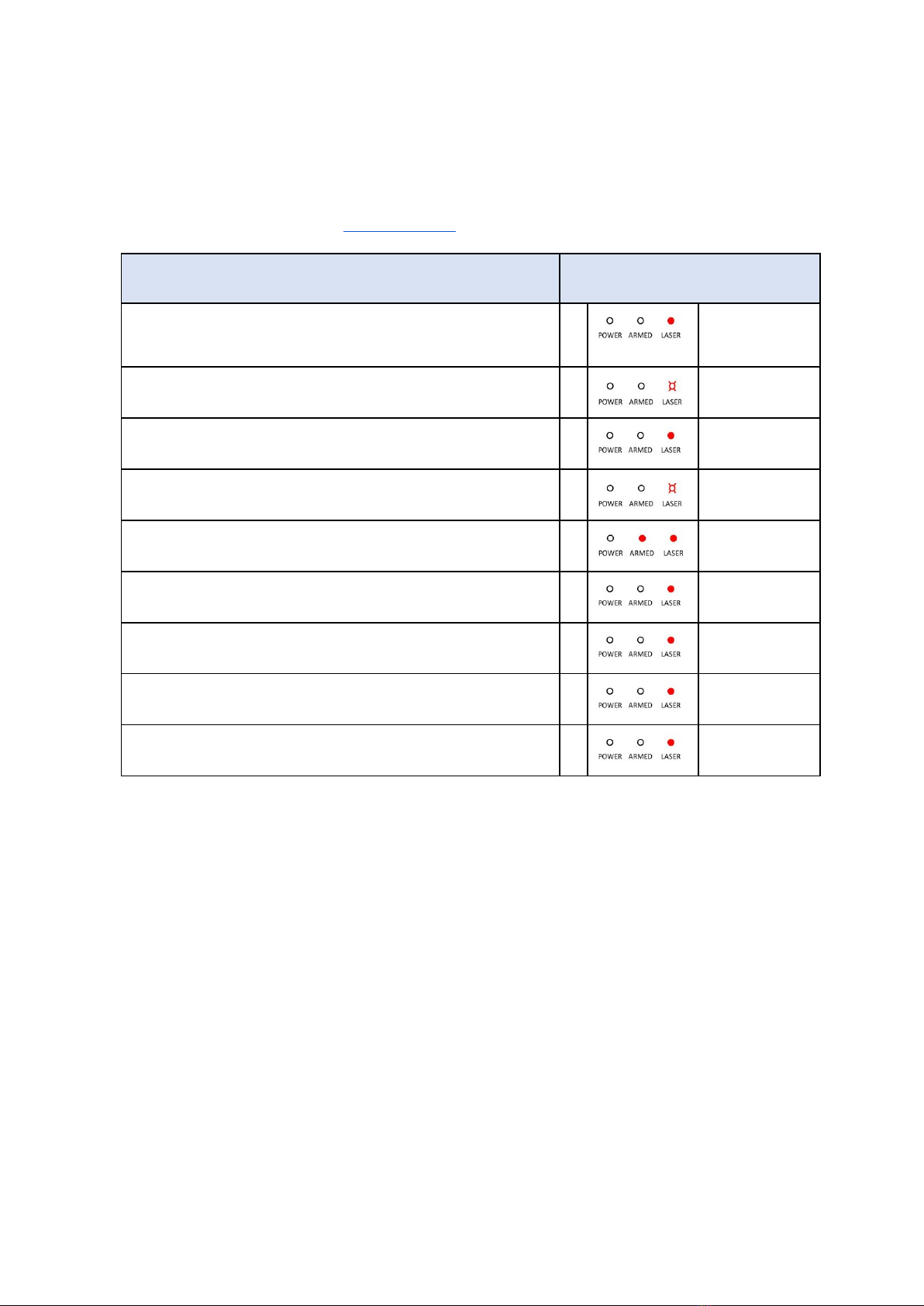
7. LED STATUS INDICATORS
The POWER LED shows the presence of power and also signals supply errors.
The ARMED LED shows the arming state and also signals both disarming by an external switch and disconnecting
the laser head.
The LASER LED shows the presence of the laser head controlling signal (a steady one or a pulse-like). Note that
controlling the laser head is disabled in the disarmed state.
In configuration mode, the LEDs show the current “enable option”. Refer to section For Advanced Users.
8. KEY SWITCH
Turn the key switch clockwise to the upper position to switch the PLH3D-CNC Adapter on.
Turn the key switch counterclockwise to the left position to switch the PLH3D-CNC Adapter off.

6
Application
Main States of the PLH3D-CNC Adapter
Power supply turned off
Power supply turned on, laser head disarmed
Laser head armed, no controlling
Laser head armed, controlling

7
Dimensions

8
Pinout

9
PLH3D-CNC Adapter settings
The table below shows the settings of the “enable options” for widely used machines.
The PLH3D-CNC Adapter is shipped with the enable options already matching the user’s machine. Checking and changing the
enable option is explained in the section For Advanced Users.
Machine
Enable options
X-Carve
0
ENABLE1=any
ENABLE2=any
Stepcraft
7
ENABLE1=LOW
ENABLE2=HIGH
Shapeoko
0
ENABLE1=any
ENABLE2=any
Z-Morph
7
ENABLE1=LOW
ENABLE2=HIGH
Workbee with Duet Controller
2
ENABLE1=HIGH
ENABLE2=any
Workbee with CNC xPro Controller
0
ENABLE1=any
ENABLE2=any
Smooth Stepper
0
ENABLE1=any
ENABLE2=any
BlackBox Motion Control System
0
ENABLE1=any
ENABLE2=any
Most cases not covered above
0
ENABLE1=any
ENABLE2=any

10
Connections to CNC machines
1.1. X-Carve
1.2. Stepcraft
Andere Handbücher für PLH3D-CNC Adapter
1
Dieses Handbuch passt für folgende Modelle
1
Inhaltsverzeichnis
Andere Opt Lasers 3D-Drucker Handbücher


