
Panaconic TH-L55ET5R Bedienungsanleitung
© Panasonic Corporation 2012. Unauthorized
copying and distribution is a violation of law.
ORDER NO. MTV1207183CE
LED TV
Model No. TH-L55ET5R
Chassis: LA35
Destination: IRAN
TABLE OF CONTENTS
PAGE PAGE
1 Safety Precautions----------------------------------------------- 3
1.1. General Guidelines---------------------------------------- 3
1.1.1. Leakage Current Cold Check---------------------- 3
1.1.2. Leakage Current Hot Check (See Figure
1.) --------------------------------------------------------- 3
2 Warning -------------------------------------------------------------- 4
2.1. Prevention of Electrostatic Discharge (ESD)
to Electrostatically Sensitive (ES) Devices---------- 4
2.2. About lead free solder (PbF)---------------------------- 5
3 Service Navigation ----------------------------------------------- 6
3.1. Service Hint ------------------------------------------------- 6
4 Specifications ----------------------------------------------------- 7
5 Service Mode ------------------------------------------------------ 9
5.1. How to enter into Service Mode ----------------------- 9
5.1.1. Contents of adjustment mode --------------------- 9
5.1.2. How to exit---------------------------------------------- 9
5.2. SRV-TOOL -------------------------------------------------10
5.2.1. How to access ----------------------------------------10
5.2.2. Display of SOS History -----------------------------10
5.2.3. POWER ON TIME/COUNT -----------------------10
5.2.4. Exit ------------------------------------------------------ 10
5.2.5. Self Check Mode ------------------------------------ 11
5.2.6. Hotel Mode Adjustment---------------------------- 11
5.2.7. Hotel Mode-------------------------------------------- 11
6 Troubleshooting Guide --------------------------------------- 12
6.1. Check of the IIC bus lines------------------------------ 12
6.1.1. How to access --------------------------------------- 12
6.1.2. Exit ------------------------------------------------------ 12
6.1.3. Screen display --------------------------------------- 12
6.2. Power LED Blinking timing chart --------------------- 13
6.3. No Power--------------------------------------------------- 13
7 Disassembly and Assembly Instructions--------------- 14
7.1. Speaker & Screw Fixing-------------------------------- 14
7.2. LCD Panel Preparation 1 ------------------------------ 15
7.3. LCD Panel Preparation 2 ------------------------------ 16
7.4. LED Panel Assembly------------------------------------ 17
7.5. Barrier and PCB Fixing --------------------------------- 18
7.6. EMI - Sticking Sponge ---------------------------------- 19
7.7. Fixing Bottom Metal ------------------------------------- 20
7.8. Back Cover Screw --------------------------------------- 21

TH-L55ET5R
2
8 Measurements and Adjustments -------------------------- 22
8.1. Voltage chart of A-board-------------------------------- 22
9 Block Diagram --------------------------------------------------- 23
9.1. Main Block Diagram ------------------------------------- 23
9.2. Detailed Block Diagram (1/2)-------------------------- 24
9.3. Detailed Block Diagram (2/2)-------------------------- 25
10 Wiring Connection Diagram --------------------------------- 26
10.1. Wire Dressing 1------------------------------------------- 26
10.2. Wire Dressing 2------------------------------------------- 27
10.3. Wire Dressing 3------------------------------------------- 28
11 Schematic Diagram--------------------------------------------- 29
12 Printed Circuit Board ------------------------------------------ 47
13 Exploded View and Replacement Parts List ----------- 53
13.1. Exploded View and Mechanical Replacement
Parts List --------------------------------------------------- 53
TH-L55ET5R
3
1 Safety Precautions
1.1. General Guidelines
1. When servicing, observe the original lead dress. If a short circuit is found, replace all parts which have been overheated or
damaged by the short circuit.
2. After servicing, see to it that all the protective devices such as insulation barriers, insulation papers shields are properly
installed.
3. After servicing, make the following leakage current checks to prevent the customer from being exposed to shock hazards.
4. When conducting repairs and servicing, do not attempt to modify the equipment, its parts or its materials.
5. When wiring units (with cables, flexible cables or lead wires) are supplied as repair parts and only one wire or some of the
wires have been broken or disconnected, do not attempt to repair or re-wire the units. Replace the entire wiring unit instead.
6. When conducting repairs and servicing, do not twist the Faston connectors but plug them straight in or unplug them straight
out.
1.1.1. Leakage Current Cold Check
1. Unplug the AC cord and connect a jumper between the
two prongs on the plug.
2. Measure the resistance value, with an ohmmeter,
between the jumpered AC plug and each exposed
metallic cabinet part on the equipment such as
screwheads, connectors, control shafts, etc. When the
exposed metallic part has a return path to the chassis, the
reading should be 100 Mohm and over.
When the exposed metal does not have a return path to
the chassis, the reading must be .
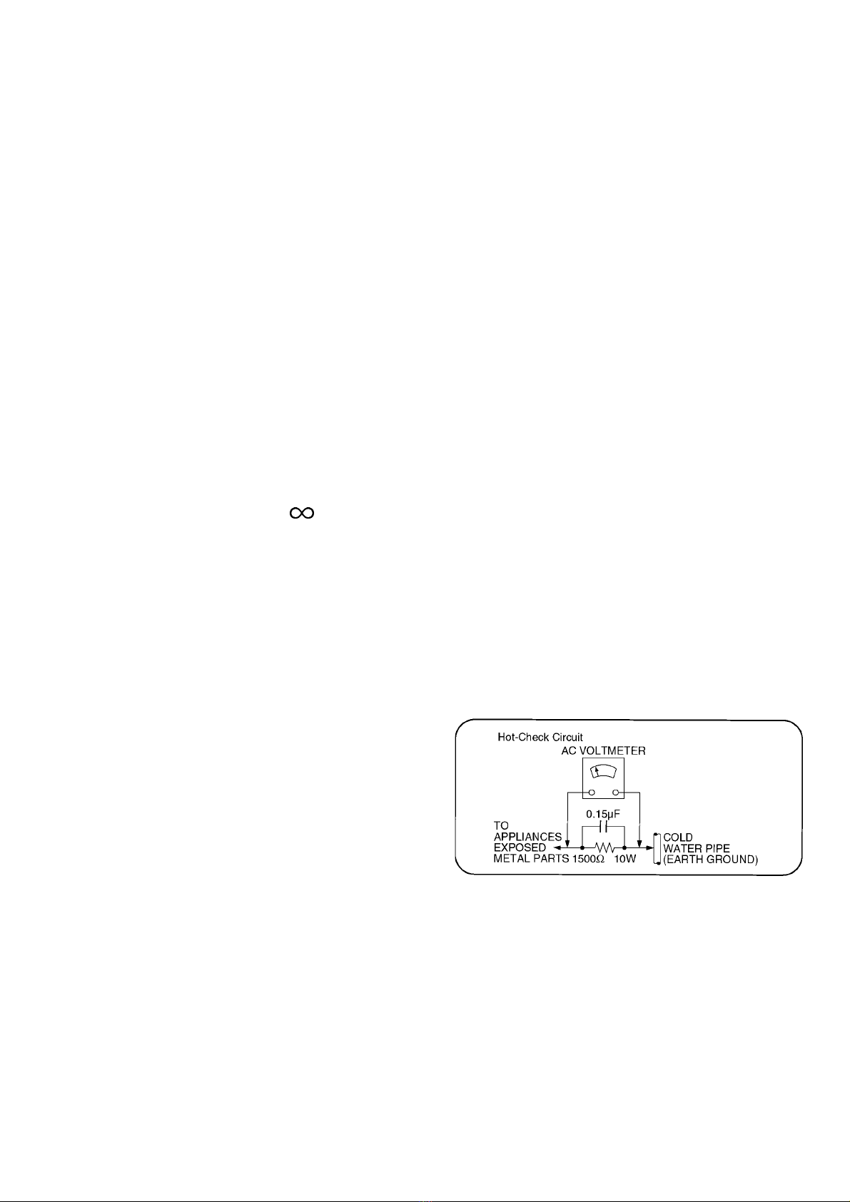
1.1.2. Leakage Current Hot Check (See
Figure 1.)
1. Plug the AC cord directly into the AC outlet. Do not use
an isolation transformer for this check.
2. Connect a 1.5kohm, 10 watts resistor, in parallel with a
0.15F capacitors, between each exposed metallic part
on the set and a good earth ground such as a water pipe,
as shown in Figure 1.
3. Use an AC voltmeter, with 1000 ohms/volt or more
sensitivity, to measure the potential across the resistor.
4. Check each exposed metallic part, and measure the
voltage at each point.
5. Reverse the AC plug in the AC outlet and repeat each of
the above measurements.
6. The potential at any point should not exceed 0.75 volts
RMS. A leakage current tester (Simpson Model 229 or
equivalent) may be used to make the hot checks, leakage
current must not exceed 1/2 milliamp. In case a
measurement is outside of the limits specified, there is a
possibility of a shock hazard, and the equipment should
be repaired and rechecked before it is returned to the
customer.
Figure 1

TH-L55ET5R
4
2Warning
2.1. Prevention of Electrostatic Discharge (ESD) to Electrostatically
Sensitive (ES) Devices
Some semiconductor (solid state) devices can be damaged easily by static electricity. Such components commonly are called
Electrostatically Sensitive (ES) Devices. Examples of typical ES devices are integrated circuits and some field-effect transistors and
semiconductor [chip] components. The following techniques should be used to help reduce the incidence of component damage
caused by electrostatic discharge (ESD).
1. Immediately before handling any semiconductor component or semiconductor-equipped assembly, drain off any ESD on your
body by touching a known earth ground. Alternatively, obtain and wear a commercially available discharging ESD wrist strap,
which should be removed for potential shock reasons prior to applying power to the unit under test.
2. After removing an electrical assembly equipped with ES devices, place the assembly on a conductive surface such as
aluminum foil, to prevent electrostatic charge buildup or exposure of the assembly.
3. Use only a grounded-tip soldering iron to solder or unsolder ES devices.
4. Use only an anti-static solder removal device. Some solder removal devices not classified as [anti-static (ESD protected)] can
generate electrical charge sufficient to damage ES devices.
5. Do not use freon-propelled chemicals. These can generate electrical charges sufficient to damage ES devices.
6. Do not remove a replacement ES device from its protective package until immediately before you are ready to install it. (Most
replacement ES devices are packaged with leads electrically shorted together by conductive foam, aluminum foil or
comparable conductive material).
7. Immediately before removing the protective material from the leads of a replacement ES device, touch the protective material
to the chassis or circuit assembly into which the device will be installed.
Caution
Be sure no power is applied to the chassis or circuit, and observe all other safety precautions.
8. Minimize bodily motions when handling unpackaged replacement ES devices. (Otherwise ham less motion such as the
brushing together of your clothes fabric or the lifting of your foot from a carpeted floor can generate static electricity (ESD)
sufficient to damage an ES device).
TH-L55ET5R
5
2.2. About lead free solder (PbF)
Note: Lead is listed as (Pb) in the periodic table of elements.
In the information below, Pb will refer to Lead solder, and PbF will refer to Lead Free Solder.
The Lead Free Solder used in our manufacturing process and discussed below is (Sn+Ag+Cu).
That is Tin (Sn), Silver (Ag) and Copper (Cu) although other types are available.
This model uses Pb Free solder in it’s manufacture due to environmental conservation issues. For service and repair work, we’d
suggest the use of Pb free solder as well, although Pb solder may be used.
PCBs manufactured using lead free solder will have the PbF within a leaf Symbol PbF stamped on the back of PCB.
Caution
• Pb free solder has a higher melting point than standard solder. Typically the melting point is 50 ~ 70 F (30~40 C) higher. Please
use a high temperature soldering iron and set it to 700 ± 20 F (370 ± 10 C).
• Pb free solder will tend to splash when heated too high (about 1100 F or 600 C).
If you must use Pb solder, please completely remove all of the Pb free solder on the pins or solder area before applying Pb
solder. If this is not practical, be sure to heat the Pb free solder until it melts, before applying Pb solder.
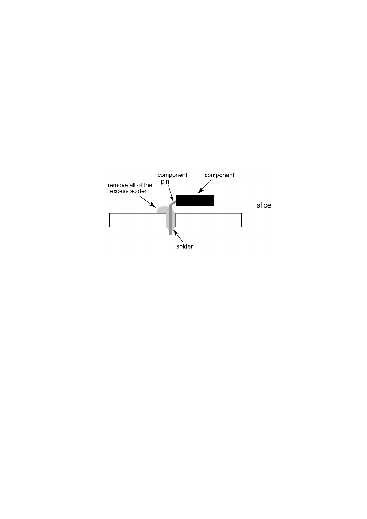
• After applying PbF solder to double layered boards, please check the component side for excess solder which may flow onto the
opposite side. (see figure below)
TH-L55ET5R
6
3 Service Navigation
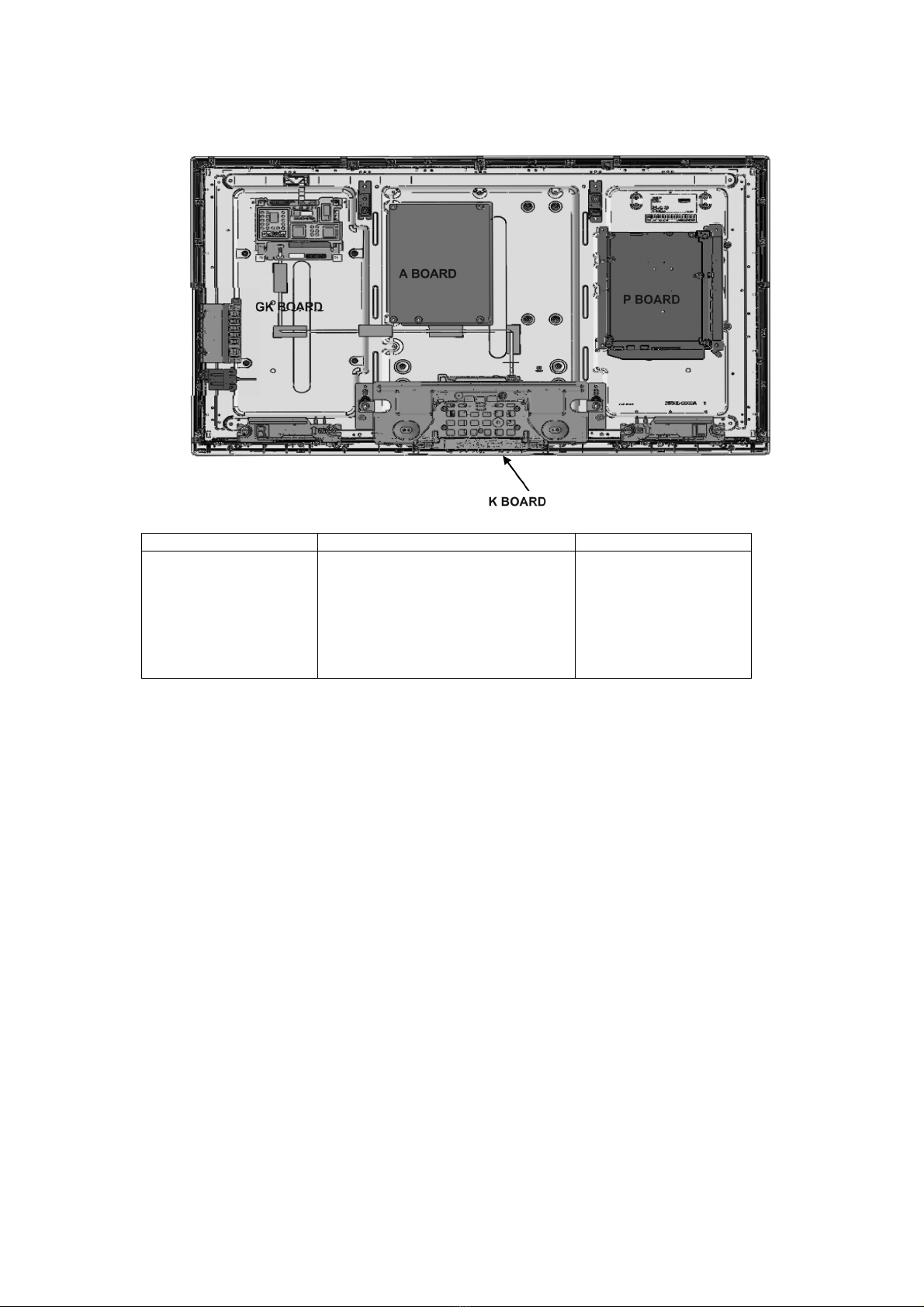
3.1. Service Hint
Board Name Main Device Remarks
A BOARD TUN, OFDM, ADV, LD4, STBY EEP Repairable
P BOARD Power Supply Repairable
K BOARD LED/RM/CATS Repairable
GK BOARD Function SW for LGD panel Repairable

TH-L55ET5R
7
4 Specifications
Power Source AC 220-240 V, 50 / 60 Hz
Power Consumption
Power Rating 170 W
Standby Condition 0.2 W
Display panel
Panel system IPS LED backlight Liquid Crystal Display
Visible screen size (diagonal) 139 cm
Number of pixels 2,073,600 (1,920 (W) 1,080 (H))
Dimensions (W H D) 1,281 mm 811 mm 282 mm (With Pedestal)
1,281 mm 765 mm 52 mm (TV only)
Mass 28.5 kg Net (With Pedestal)
25.0 kg Net (TV only)
Sound
Speaker (75 mm 22 mm) 2, 8
Audio Output 20 W (10 W + 10 W)
Headphones M3 (3.5 mm) stereo mini Jack 1
Receiving Systems / Band name 17 SYSTEMS FUNCTIONS
1PAL B, G, H
Reception of broadcast transmission and
playback from video cassette tape recorders.
2PAL I
3PAL D, K
4SECAM B, G
5SECAM D, K
6SECAM K1
7NTSC M (NTSC 3.58 / 4.5MHz)
8NTSC 4.43 / 5.5 MHz
Playback from special VCR’s or DVD.
9NTSC 4.43 / 6.0 MHz
10 NTSC 4.43 / 6.5 MHz
11 NTSC 3.58 / 5.5 MHz
12 NTSC 3.58 / 6.0 MHz
13 NTSC 3.58 / 6.5 MHz
14 SECAM I
15 PAL 60 Hz / 5.5 MHz Playback from Special Disc Players and
Special VCR’s or DVD.
16 PAL 60 Hz / 6.0 MHz
17 PAL 60 Hz / 6.5 MHz
Receiving Channels (Analogue TV)
VHF BAND 2 - 12 (PAL / SECAM B, K1)
0 - 12 (PAL B AUST.)
1 - 9 (PAL B N.Z.)
1 - 12 (PAL / SECAM D)
1 - 12 (NTSC M JAPAN)
2 - 13 (NTSC M USA)
UHF BAND 21 - 69 (PAL G, H, I / SECAM G, K, K1)
28 - 69 (PAL B AUST.)
13 - 57 (PAL D, K)
13 - 62 (NTSC M JAPAN)
14 - 69 (NTSC M USA)
CATV S1 - S20 (OSCAR)
1 - 125 (USA CATV)
C13 - C49 (JAPAN)
S21 - S41 (HYPER)
Z1 - Z37 (CHINA)
5A, 9A (AUST.)
Aerial - Rear VHF / UHF
Operating Conditions Temperature : 0C - 40C
Humidity : 20 % - 80 % RH (non-condensing)

TH-L55ET5R
8
Note
• Design and Specifications are subject to change without notice. Mass and Dimensions shown are approximate.
Connection Terminals
AV1 IN AUDIO L-R RCA PIN Type 2 0.5 V[rms]
VIDEO RCA PIN Type 1 1.0 V[p-p] (75 )
AUDIO OUT AUDIO L-R RCA PIN Type 2 0.5 V[rms] (high impedance)
AV2 IN AUDIO L-R RCA PIN Type 2 0.5 V[rms]
COMPONENT Y 1.0 V[p-p] (including impedance)
PB/CB, PR/CR±0.35 V[p-p]
VIDEO RCA PIN Type 1 1.0 V [p-p] (75 )
HDMI 1 / 2 / 3 / 4 input TYPE A Connectors
• This TV supports ‘HDAVI Control 5’ function.
PC
HIGH-DENSITY D-SUB 15 PIN
R, G, B: 0.7 V[p-p] (75 )
HD, VD: TTL LEVEL 2.0-5.0 V [p-p] (high impedance)
• Applicable input signals:
VGA, SVGA, WVGA, XGA, SXGA, WXGA
Card Slot SD Card slot 1
ETHERNET 10BASE-T / 100BASE-TX
USB 1 / 2 / 3
USB 2.0 TYPE A Connectors
DC 5 V, Max. 500 mA
DIGITAL AUDIO OUT PCM / Dolby Digital, Fibre optic
3D Eyewear
Dimensions (W × H × D) 149.0 mm 44.0 mm 171.0 mm
Mass Approx. 18 g
Lens type Circularly-polarised filter
Usage temperature range 0 °C - 40 °C
Materials Main body: Resin
Lens section: Resin
TH-L55ET5R
9
5 Service Mode
5.1. How to enter into Service Mode
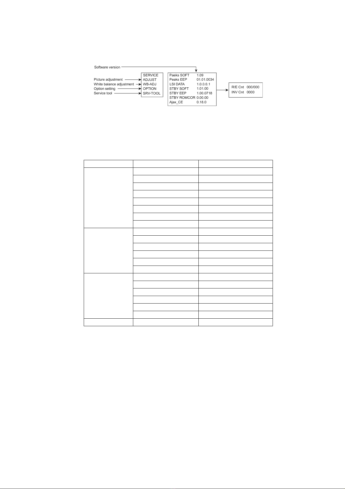
While pressing [VOLUME ( - )] button of the main unit, press [INFO] button of the remote control three times within 2 seconds.
5.1.1. Contents of adjustment mode
• Value is shown as a hexadecimal number.
• Preset value differs depending on models.
• After entering the adjustment mode, take note of the value in each item before starting adjustment.
5.1.2. How to exit
Switch off the power with the [POWER] button on the main unit or the [POWER] button on the remote control.
Main item Sub item Sample Data
ADJUST CONTRAST 000
COLOR 59
TINT FE
SUB-BRT 800
BACKLGT 20D
B-Y-G 40
R-Y-A 0
VCOM 189
WB-ADJ R-GAIN 75
G-GAIN 80
B-GAIN 65
R-CENT 80
G-CENT 80
B-CENT 9B
OPTION Boot ROM
STBY-SET 00
EMERGENCY ON
CLK MODE 00
CLOCK FC7
EDID-CLK HIGH
SRV-TOOL 00
TH-L55ET5R
10
5.2. SRV-TOOL
5.2.1. How to access
1. Select [SRV-TOOL] in Service Mode.
2. Press [OK] button on the remote control.
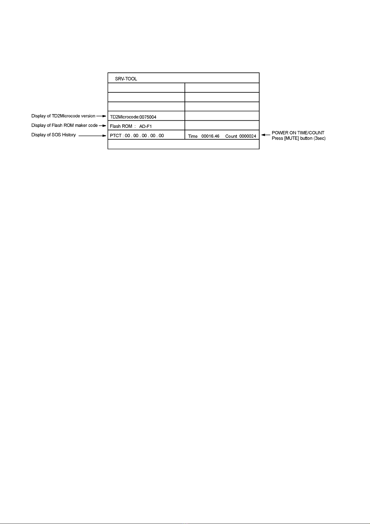
5.2.2. Display of SOS History
SOS History (Number of LED blinking ) indication.
From left side; Last SOS, before Last, three occurrence before, 2nd occurrence after shipment, 1st occurrence after shipment.
This indication except 2nd and 1st occurrence after shipment will be cleared by [Self-check indication and forced to factory
shipment setting].
5.2.3. POWER ON TIME/COUNT
Note : To display TIME/COUNT menu, highlight position, then press MUTE for 3sec.
Time : Cumulative power on time, indicated hour : minute by decimal
Count : Number of ON times by decimal
Note : This indication will not be cleared by either of the self-checks or any other command.
5.2.4. Exit
1. Disconnect the AC cord from wall outlet.
Dieses Handbuch passt für folgende Modelle
1
Inhaltsverzeichnis


