
Paradox PCS250 Bedienungsanleitung


Table of Contents
Introduction.......................................................... 4
Features............................................................................... 4
Overview................................................................ 6
System Components ......................................................6
LED Feedback ....................................................................7
Specifications ....................................................................8
Connections .........................................................9
SIM Card Connection ......................................................9
Optional Power Supply Connections .................... 11
VDMP3 Connection
(Optional - GSM mode only)..................................... 12
Using an RS485 Link..................................................... 13
Using an External Power Input ................................ 14
Antenna Installation ....................................... 15
Antenna Extension Installation (Optional) .......... 15
Configuring the PCS250 ................................ 16
Frequency Band ............................................................ 16
Bandwidth Saver Mode .............................................. 16
Configuring GSM Network Provider
Information ..................................................................... 16
Configuring WinLoad Access ................................... 17
Programming and Registering GPRS
Reporting Options ........................................................ 18
SMS Backup Reporting ............................................... 20
Troubles ........................................................................... 22
SMS Language ............................................................... 23
Arm/Disarm System via Text Message ..................24
List of SMS Commands ............................................... 25
Upload/Download .......................................... 26
Public Network (GPRS mode only) ......................... 26
Private Network ............................................................. 26
Module Supervision ........................................ 28
View GSM IP Information ........................................... 30
Text Messages ................................................... 32

Page 4 Introduction
Chapter 1: Introduction
The PCS250 provides Paradox control panels with wireless
communication capabilities to report system events through a
GPRS or GSM network to the IPR512 GPRS/IP Monitoring
Receiver.
The PCS250 can be configured to send system events to the end-
user via SMS. All this is achieved via a simple 4-wire serial
connection between the control panel and the PCS250.
The PCS250 can be installed up to 2m (6 ft.) from the panel. An
external antenna can be installed up to 18m (60 ft.) from the
reporting device using an optional antenna and a cable
extension, depending on the local signal strength.
Features
• Report events to the IPR512 GPRS/IP Monitoring Receiver
via GPRS or to a landline receiver via GSM
• Report via text message (up to 16 cell phone numbers)
• Control panel communication supervision. When detected,
the control panel will generate a trouble as well as report it
to the monitoring station via landline
• End user can arm or disarm the system by sending a text
message (SMS) to the PCS250
• Send pre-recorded voice messages to up to 8 phone
numbers to report alarms using the Paradox Plug-In Voice
Module (VDMP3) - GSM mode
• Simple installation with 4-wire serial connection
• Optional rod antenna can be installed up to 18m (60ft) from
the module using optional antenna cable extensions
depending on the local signal strength
• 128-bit (MD5) and 256-bit (AES) encryption - GPRS mode
• Increase the distance between the panel and the PCS250
with an RS485 link (GSM mode only (e-bus)). A CVT485
module must be added at the panel in order to accomplish
this.

Introduction Page 5
Included Items
•Serialcable
•GPRS14Module
Required/Optional Items
• Active SIM card (required)
• Paradox Plug-In Voice Module VDMP3 (optional)
• Antenna extension (optional)
• 12 Vdc external power supply (optional)
Compatibility
• EVO48 and EVO192 panels V2.02
• K641 and K641R keypads V1.51 or higher
• SP series V3.42 with K32LCD keypads V1.22
• E55 panels V3.0 (labels to be programmed via Winload)
• E65 panels V2.1 (labels to be programmed via Winload)
• MG series V4.0 or higher with K32LCD keypads V1.22 or higher
For latest updates visit paradox.com
Page 6 Overview
Chapter 2: Overview
This section provides an overview of the Paradox PCS250
Communicator Module. It covers technical specifications, light-
emitting diode (LED) functionality, and an overview of the
PCS250 system components.
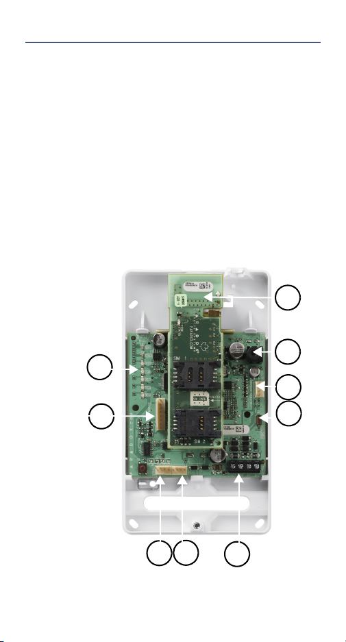
System Components
1) GPRS14 with dual SIM card slots
2) Audio jack
3) InField upgrade connector
4) Function switch reserved for future use
5) RS485/power terminal
6) Future use
7) Serial cable connector
8) Audio module connector (e.g., VDMP3)
9) System LEDs (refer to “LED Feedback” on page 7)
1
2
3
4
765
8
9

Overview Page 7
LED Feedback
The following table provides a description of the PCS250
Communicator Module LEDs.
Communication Loss
Upon loss of communication with the panel, the PCS250 LEDs
will behave in the following manner:
1) GPRS or GSM LED displays are off; the SIM card and Signal
Strength LEDs display their status for about 3 seconds.
2) Signal strength LED remains OFF; GSM (green) is turned ON,
followed in turn by GPRS (green), SIM2 (orange) and SIM1
(red). When a LED is ON, all others are off. Each LED lights for
about 20 sec. This sequence is repeated two times.
3) This cycle repeats until communication is restored.
LED Feedback
SIM
Card 1
Solid green = SIM card 1 is installed on the GPRS14
Quick green flashing = SIM card 1 is exchanging
data
Slow green flashing = Searching the network
Solid red = SIM card 1 is defective
Off = SIM card 1 is not present
SIM
Card 2
Future use
GPRS Solid green = unit is set for GSM operation
Quick green flashing = exchanging data
Note: When this LED is ON, the GSM LED stays OFF.
GSM Solid green = unit is set for GSM operation
Quick green flashing = exchanging data
Note: When this LED is ON, the GSM LED stays OFF.
Signal
Strength
LED 1, 2, and 3 (bottom three LEDs) indicate the
strength of the incoming antenna signal.

Page 8 Overview
Specifications
The following table describes the technical specifications of the
PCS250 Communicator Module.
Power Class 4 (2W) @ 850/900 MHz
Class 2 (1W) @ 1800/1900 MHz
Antenna
Bandwidth
70 / 80 / 140 / 170 MHz
Antenna Gain <3dBi; impedance 50 ohm
Input power >2W peak power
Power Input 12Vdc nominal
Consumption 100 mA standby, average 450mA (1.2A
peak) during GPRS/GSM transmission
Operating
Temperature
0ºC to 50ºC (32ºF to 122ºF)
Encryption 128-bit (MD5 and RC4) or 256-bit (AES)
SMS Protocol 8-bit (IRA:ITU-T.50) or 16-bit (UCS2 ISO/
IEC10646)

Connections Page 9
Chapter 3: Connections
The following sections guide you through the steps required to
connect the PCS250 prior to mounting the unit.
SIM Card Connection
The PCS250 connects to your Paradox control panel providing
wireless communication capabilities to report system events to a
monitoring station. The PCS250 supports standard GSM provider
SIM cards. The SIM card contains all your cellular telephone
account information. In order to activate your SIM card, you must
contact your local GSM network provider. It is important to use
SIM Card Tray 1, as SIM Card Tray 2 is reserved for future use.
Note: Prior to setting up your PCS250, it is important that the
Personal Identification Number (PIN) of the SIM card be disabled.
Refer to your cellular phone’s manual for more information on how
to disable the PIN.
To install the SIM card:
1) Remove the front cover of the PCS250 Module. If the cover
is not installed, proceed to Step 2.
2) If an optional VDMP3 module is installed, disconnect the
VDMP3 before proceeding to the next step.
3) Slide the SIM card tray towards the bottom to unlock it, and
then flip the SIM card tray open towards you, as shown in
Figure 1.
Note: Open the SIM tray slowly to avoid damage to the tray.

Page 10 Connections
4) Slide the SIM card into the tray with the cut-off corner
towards the bottom left. Close the SIM card tray and slide
the tray up to lock it into place.
5) Reconnect the VDMP3 module.
Figure 1: SIM Card Installation
Andere Handbücher für PCS250
2
Inhaltsverzeichnis
Andere Paradox Handy Handbücher

Paradox
Paradox PCS200 Bedienungsanleitung

Paradox
Paradox PCS250 Installationsanleitung

Paradox
Paradox PCS250 Bedienungsanleitung

Paradox
Paradox PCS265LTE Installationsanleitung

Paradox
Paradox PCS265 LTE Bedienungsanleitung

Paradox
Paradox PCS250G Bedienungsanleitung

Paradox
Paradox PCS260 Installationsanleitung
Beliebte Handy Handbücher anderer Marken


Point Mobile
Point Mobile PM60 Bedienungsanleitung

Blackbe;rry
Blackbe;rry Q10 Bedienungsanleitung

Blackbe;rry
Blackbe;rry Bold 9900 Bedienungsanleitung

Blackbe;rry
Blackbe;rry STORM 9500 - VERSION 5.0 Bedienungsanleitung

LG
LG LM-K420EMW Bedienungsanleitung

ISAFE MOBILE
ISAFE MOBILE IS655.2 Bedienungsanleitung