
Paradyne 5011 Bedienungsanleitung

TM
1
5020-A2-GN10-20 March 1998
Hotwire5020 POTS Splitter Central Office
Installation Instructions
Document Number 5020-A2-GN10-20
March 1998
About the Hotwire5020 RADSL POTS Splitter
The Hotwire RADSL System enables simultaneous high-speed digital data
access and analog voice service over the same twisted-pair telephone line. The
simultaneous access to RADSL (Rate Adaptive Digital Subscriber Line) and
POTS (Plain Old Telephone Service) requires the installation of a POTS splitter
at both ends of the local loop; i.e., at the central office (CO) and at the customer
premises (CP).
The POTS splitter filters out the DSL signal and allows the POTS frequencies to
pass through. Each central office POTS splitter card contains 12 filters to serve
12 local loops with DSL-based service and POTS. The POTS splitter card is a
passive device and requires no power. The POTS splitter chassis is shipped
separately from the POTS splitter card(s). Two chassis are available:
Single-card chassis which can be placed on a tabletop or installed in a rack.
Six-card chassis which must be installed in a commercial EIA-standard
19″or 23″rack or cabinet.
Before You Begin
Consider the following before installing the POTS splitter:
Installation Site
The location should be well-ventilated, clean, and free of environmental
extremes. Allow clearance at the front of the POTS splitter chassis to provide
access to the cables.
Cabling
Three Telco 50-conductor cables are used to connect to the three interfaces
on the POTS splitter card. The location of the system hardware affects the
length of the three cables.
Cables and Hardware You Need
For each POTS splitter card, obtain three Telco 50-conductor cables with
50-position amphenol-type connectors at the appropriate length based on cabling
requirements in your environment. A Y-cable is available for the DSL connection.
Refer to
Cabling Overview
,page 11, and
Connector Pin Numbers,
page 17.

2 5020-A2-GN10-20
March 1998
Hotwire 5020 POTS Splitter Card Package Checklist
Verify that your POTS splitter card package contains the following:
POTS splitter card
Plastic bag with three of each item:
— Plastic tie-wrap anchors
— #4-40 x 1/4″screws
— #4-40 x 1/4″jack screws
—8″cable tie wraps
Warranty card
Single-Card 5011 POTS Splitter Chassis Package Checklist
Verify that your single-card POTS splitter chassis package contains the following:
Single-card POTS splitter chassis
Two brackets for 19″racks and two brackets for 23″racks
Small plastic bag with:
— Six #10-32 x 1/4″Phillips flat-head mounting screws
— Four #10-32 x 1/2″Phillips-head mounting screws
— Four #12-24 x 1/2″Phillips-head mounting screws
— Four #12-24 speed nuts
— Four black rubber feet
Warranty card
97-15497
CO POTS Splitter
Single-Card Chassis
Placement of
Rubber
Feet
3
5020-A2-GN10-20 March 1998
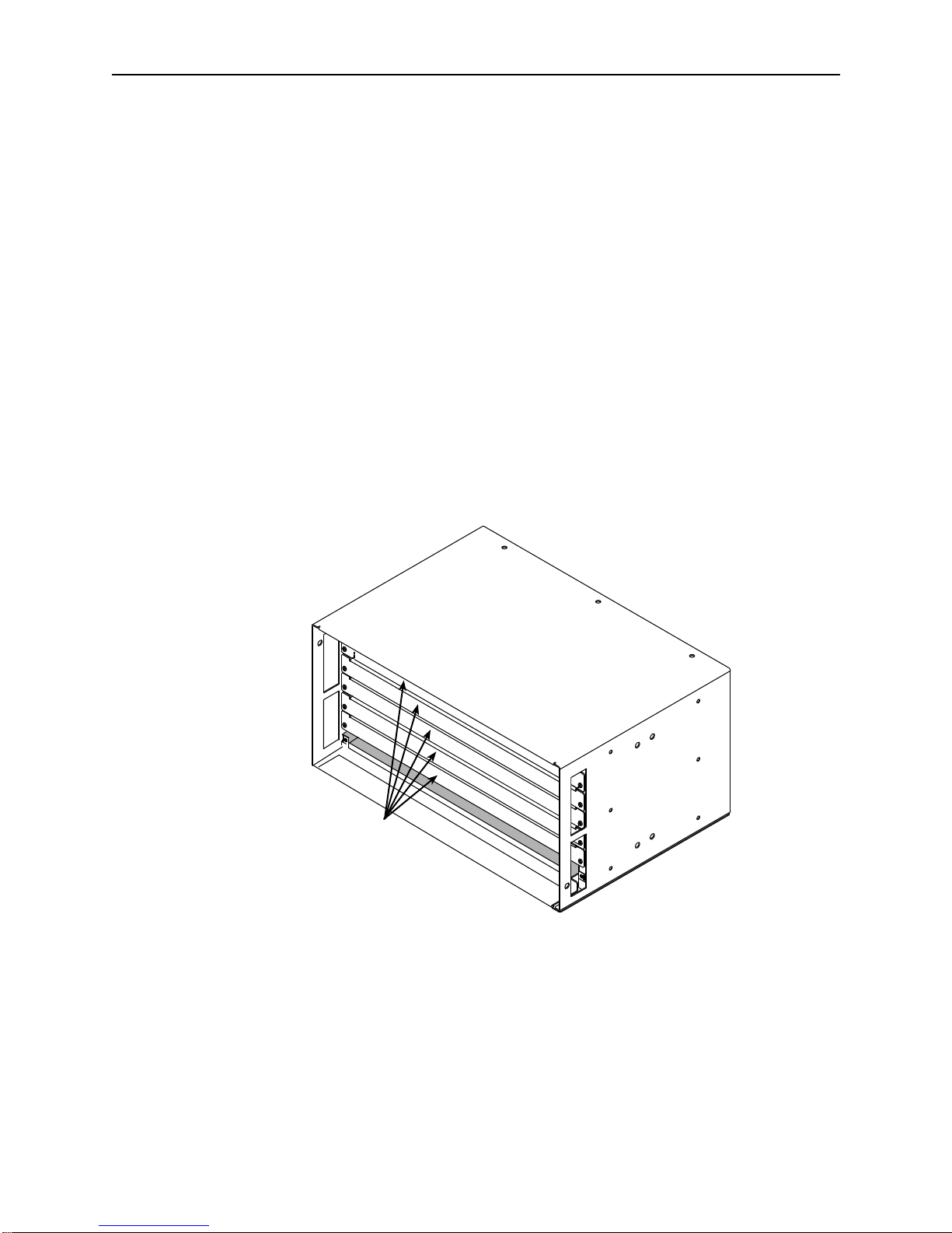
Six-Card 5016 POTS Splitter Chassis Package Checklist
Verify that your six-card POTS splitter chassis package contains the following:
-Six-card POTS splitter chassis with five filler panels. Each filler panel is
attached to the chassis with two 1/4-turn fasteners. Keep filler panels
installed in all unused slots.
-Two brackets for 19″racks and two brackets for 23″racks
-Small plastic bag with:
— Six #10-32 x 1/4″Phillips flat-head mounting screws
— Four #10-32 x 1/2″Phillips-head mounting screws
— Four #12-24 x 1/2″Phillips-head mounting screws
— Four #12-24 speed nuts
— Four black rubber feet (discard)
-Warranty card
97-15430
CO POTS Splitter
Six-Card Chassis
Filler
Panels
Tools Required
HA small #1 or #2 Phillips screwdriver to tighten the POTS splitter card
fasteners.
HA large #3 or #4 Phillips screwdriver to install the chassis into a rack.
HA flat-blade screwdriver to install the chassis grounding wire.

4 5020-A2-GN10-20
March 1998
Product-Related Documents
The 5020 CO POTS splitter card works in conjunction with the Hotwire 8540 or
8546 RADSL card in the central office in the 8600 or 8800 DSLAM chassis, and
a POTS splitter and Remote Termination Unit (RTU) at the customer premises.
Refer to the following documents for product-specific information.
Document Number Document Title
5030-A2-GN10
Hotwire 5030 POTS Splitter Customer Premises
Installation Instructions
5034-A2-GN10
Hotwire 5034 Indoor POTS Splitter Customer Premises
Installation Instructions
5038-A2-GN10
Hotwire 5038 Distributed POTS Splitter Customer
Premises Installation Instructions
5216-A2-GN10
Hotwire 5216 Remote Termination Unit (RTU) Customer
Premises Installation Instructions
5246-A2-GN10
Hotwire 5246 Remote Termination Unit (RTU) Customer
Premises Installation Instructions
5446-A2-GN10
Hotwire 5446 Remote Termination Unit (RTU) Customer
Premises Installation Instructions
5620-A2-GN10
Hotwire 5620 Remote Termination Unit (RTU) Customer
Premises Installation Instructions
8540-A2-GN10
Hotwire 8540 Digital Subscriber Line (DSL) Card
Installation Instructions
8546-A2-GN10
Hotwire 8546 Digital Subscriber Line (DSL) Card
Installation Instructions
8600-A2-GN20
Hotwire 8600 Digital Subscriber Line Access Multiplexer
(DSLAM) Installation Guide
8800-A2-GN21
Hotwire 8800 Digital Subscriber Line Access Multiplexer
(DSLAM) Installation Guide
Contact your sales or service representative to order additional product
documentation.
Paradyne documents are also available on the World Wide Web at:
http://www.paradyne.com
Select
Service & Support
→
Technical Manuals

5
5020-A2-GN10-20 March 1998
POTS Splitter Chassis Installation
The following figure provides an example of two POTS splitter chassis center
mounted in a 19″rack with two 8800 DSLAMs in a 19″cabinet.
97-15426a-0
1
ALARMS
Major MinorFanBA
POWER
AB
ALARMS
Major MinorFanBA
POWER
AB
8800
DSLAM
Chassis
Six-Card
POTS
Splitter
Chassis
19" Cabinet 19" Rack
Planning the POTS Splitter Chassis Installation
The POTS splitter chassis is shipped with mounting brackets to allow installation
in a rack that is either 19″or 23″wide. To plan the bracket and chassis
installation, determine:
Width of the rack: 19″or 23″.
Chassis position in the rack: center mounted or front mounted. Center
mounted is recommended for convenient access to cables.
Whether the rack has mounting rails with threaded or non-threaded screw
holes.
If a single-card 8600 DSLAM chassis is being placed on a table top. If so,
plan to install the rubber feet as shown on page 2. Discard rubber feet for
any rack-mounted chassis.
NOTE:
In order to reduce the risk of accidental tip over, it is strongly recommended
that the chassis be installed into the rack from the bottom up.

6 5020-A2-GN10-20
March 1998
Installing the Brackets
The brackets can be installed in the chassis in a center-mounting or
front-mounting configuration. Mounting holes are provided in the chassis for
either configuration. Install the appropriate 19″or 23″brackets on the single-card
or six-card chassis.
19-Inch Rack
23-Inch Rack
97-15486
Single-Card Chassis
19-Inch Rack
23-Inch Rack
97-15434
Front Mount
Center Mount
Six-Card Chassis
Select one of the next two procedures for chassis installation in a rack.

7
5020-A2-GN10-20 March 1998
Installation into a Rack with Threaded Screw Holes
Procedure
After installing the appropriate brackets on the chassis:
1. Determine the preferred placement of the chassis in the rack.
2. Use the four Phillips-head mounting screws provided and a Phillips
screwdriver to install the chassis.
Front Rail
97-15435
Screw
3. Tighten all four screws.
To install the next chassis in the same manner, follow Steps 1 through 3. For a
standard rack installation, chassis can be mounted directly on top of each other.
Installation into a Rack without Threaded Screw Holes
Procedure
After installing the appropriate brackets on the chassis:
1. Determine the preferred placement of the chassis in the rack.
2. Insert a speed nut onto each mounting rail hole selected and align the hole of
the speed nut with the hole in the rail.
8 5020-A2-GN10-20
March 1998
3. Use a Phillips screwdriver to install the:
— Single-card chassis in 19″or 23″rack, or a six-card chassis in a
19″rack.
— Six-card chassis in a 23″rack. Install the top two screws loosely enough
to allow the bracket’s upper keyholes to drop under the screw heads
during installation.
4. Line up the chassis-mounting bracket with the speed nut and start to rotate
the speed nut screw into the chassis mounting bracket and the speed nut.
5. Loosely install the bottom screws first and then the top screws. Tighten each
screw until the head is flush with the chassis and securely mounted in the
rack.
To install the next chassis in the same manner, follow Steps 1 through 5. For a
standard rack installation, chassis can be mounted directly on top of each other.
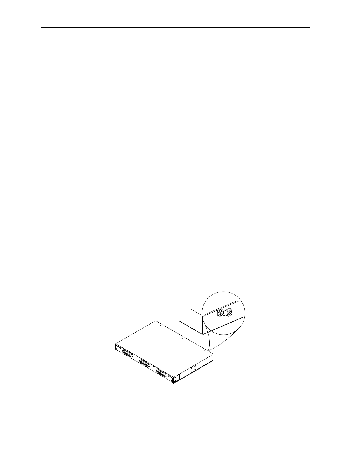
Installing the Ground Wire
To comply with National Equipment Building Standards (NEBS) requirements, the
ground wire must be installed.
Procedure
1. There is a ground lug on each chassis. Locate the ground lug.
If you have a . . . Then the ground lug is . . .
Single-card chassis On the rear of the chassis on the left.
Six-card chassis On the front of the chassis on the top right.
98-15876
CO POTS Splitter
Single-Card Chassis

9
5020-A2-GN10-20 March 1998
98-15877
CO POTS Splitter
Six-Card Chassis
2. Strip back the insulation approximately 1/4″to 3/8″on the copper wire.
If you have a . . . Then the ground wire gauge must be . . .
Single-card 5011 chassis 10 — 14 AWG.
Six-slot 5016 chassis 6 — 14 AWG.
3. Loosen the screw on the GND lug.
98-15879
4. Insert the stripped end of the wire into the open end of the GND lug and
tighten the lug’s screw. Make sure that the wire is making contact with the
stripped portion of the wire.

10 5020-A2-GN10-20
March 1998
Installing the POTS Splitter Card in the Chassis
Procedure
1. Insert the POTS splitter card into the chassis.
2. Tighten the two 1/4-turn fasteners in the faceplate for each installed POTS
splitter card.
97-15429
CO POTS Splitter
Single-Card Chassis
DSL Interface
Loop Interface
PSTN Interface
1/4-Turn
Fastener
1/4-Turn
Fastener
Dieses Handbuch passt für folgende Modelle
2
Inhaltsverzeichnis
Andere Paradyne Kabel und Steckverbinder Handbücher

Paradyne
Paradyne 3511 DSU Bedienungsanleitung

Paradyne
Paradyne BitStorm 6051 Bedienungsanleitung

Paradyne
Paradyne Hotwire 6050 Bedienungsanleitung

Paradyne
Paradyne HotWire 5034 Bedienungsanleitung

Paradyne
Paradyne Hotwire 7034 Bedienungsanleitung

Paradyne
Paradyne Hotwire 5020 Bedienungsanleitung

Paradyne
Paradyne 9261 Bedienungsanleitung

Paradyne
Paradyne 5034 Bedienungsanleitung

Paradyne
Paradyne BitStorm 6051 Bedienungsanleitung
Paradyne
Paradyne 5030 Bedienungsanleitung


