
Parker 8903/FA Bedienungsanleitung

8903/FA
FireWire IEEE 1394a
Communications Option
Technical Manual
HA469265U001 Issue 5
©Copyright 2010 Parker Hannifin Ltd.
All rights strictly reserved. No part of this document may be stored in a retrieval system, or transmitted in any
form or by any means to persons not employed by a Parker Hannifin Ltd., Automation Group, SSD Drives
Europe without written permission from Parker Hannifin Ltd., Automation Group, SSD Drives Europe. Although
every effort has been taken to ensure the accuracy of this document it may be necessary, without notice, to
make amendments or correct omissions. Parker Hannifin ltd., Automation Group, SSD Drives Europe cannot
accept responsibility for damage, injury, or expenses resulting there from.
WARRANTY
Parker Hannifin Ltd., Automation Group, SSD Drives Europe, warrants the goods against defects in design, materials
and workmanship for the period of 24 months from the date of manufacture, or 12 months from the date of delivery
(whichever is the longer period) on the terms detailed in Parker SSD Drives Standard Conditions of Sale IA500504.
Parker Hannifin Ltd., Automation Group, SSD Drives Europe reserves the right to change the content and product
specification without notice.

Cont.2
FAILURE OR IMPROPER SELECTION OR IMPROPER USE OF THE PRODUCTS
DESCRIBED HEREIN OR RELATED ITEMS CAN CAUSE DEATH, PERSONAL
INJURY AND PROPERTY DAMAGE.
This document and other information from Parker-Hannifin
Corporation, its subsidiaries and authorized distributors
provide product or system options for further investigation by
users having technical expertise.
The user, through its own analysis and testing, is solely
responsible for making the final selection of the system and
components and assuring that all performance, endurance,
maintenance, safety and warning requirements of the
application are met. The user must analyze all aspects of the
application, follow applicable industry standards, and follow
the information concerning the product in the current product
catalog and in any other materials provided from Parker or its
subsidiaries or authorized distributors.
To the extent that Parker or its subsidiaries or authorized
distributors provide component or system options based upon
data or specifications provided by the user, the user is
responsible for determining that such data and specifications
are suitable and sufficient for all applications and reasonably
foreseeable uses of the components or systems.
Cont.3
Requirements
IMPORTANT: Please read this information BEFORE installing the equipment.
Intended Users
This manual is to be made available to all persons who are required to install, configure or
service equipment described herein, or any other associated operation.
The information given is intended to highlight safety issues, EMC considerations, and to enable
the user to obtain maximum benefit from the equipment.
Complete the following table for future reference detailing how the unit is to be installed and
used.
INSTALLATION DETAILS
Model Number
(see product label)
Where installed
(for your own
information)
Unit used as a:
(refer to Certification
for the Inverter)
οComponent οRelevant Apparatus
Unit fitted: οWall-mounted οEnclosure
Application Area
The equipment described is intended for industrial motor speed control utilising DC motors, AC
induction or AC synchronous machines
Personnel
Installation, operation and maintenance of the equipment should be carried out by qualified
personnel. A qualified person is someone who is technically competent and familiar with all
safety information and established safety practices; with the installation process, operation and
maintenance of this equipment; and with all the hazards involved.
Product Warnings
Caution
Risk of electric
shock
Caution
Refer to
documentation
Earth/Ground
Protective
Conductor
Terminal
Safety Information
!

Cont.4
Hazards
DANGER! - Ignoring the following may result in injury
1. This equipment can endanger life by exposure to
rotating machinery and high voltages.
2. The equipment must be permanently earthed due to the
high earth leakage current, and the drive motor must be
connected to an appropriate safety earth.
3. Ensure all incoming supplies are isolated before
working on the equipment. Be aware that there may be
more than one supply connection to the drive.
4. There may still be dangerous voltages present at power
terminals (motor output, supply input phases, DC bus
and the brake, where fitted) when the motor is at
standstill or is stopped.
5. For measurements use only a meter to IEC 61010
(CAT III or higher). Always begin using the highest
range.
CAT I and CAT II meters must not be used on this
product.
6. Allow at least 5 minutes for the drive's capacitors to
discharge to safe voltage levels (<50V). Use the
specified meter capable of measuring up to 1000V
dc & ac rms to confirm that less than 50V is present
between all power terminals and earth.
7. Unless otherwise stated, this product must NOT be
dismantled. In the event of a fault the drive must be
returned. Refer to "Routine Maintenance and
Repair".
WARNING! - Ignoring the following may result in injury or damage to equipment
SAFETY
Where there is conflict between EMC and Safety requirements, personnel safety shall always take precedence.
•Never perform high voltage resistance checks on the
wiring without first disconnecting the drive from the
circuit being tested.
•Whilst ensuring ventilation is sufficient, provide
guarding and /or additional safety systems to prevent
injury or damage to equipment.
•When replacing a drive in an application and before
returning to use, it is essential that all user defined
parameters for the product’s operation are correctly
installed.
•All control and signal terminals are SELV, i.e.
protected by double insulation. Ensure all external
wiring is rated for the highest system voltage.
•Thermal sensors contained within the motor must
have at least basic insulation.
•All exposed metalwork in the Inverter is protected
by basic insulation and bonded to a safety earth.
•RCDs are not recommended for use with this
product but, where their use is mandatory, only Type
B RCDs should be used.
EMC
•In a domestic environment this product may cause radio
interference in which case supplementary mitigation
measures may be required.
•This equipment contains electrostatic discharge (ESD)
sensitive parts. Observe static control precautions
when handling, installing and servicing this product.
•This is a product of the restricted sales distribution
class according to IEC 61800-3. It is designated as
“professional equipment” as defined in
EN61000-3-2. Permission of the supply authority
shall be obtained before connection to the low
voltage supply.
CAUTION!
APPLICATION RISK
•The specifications, processes and circuitry described herein are for guidance only and may need to be adapted to the
user’s specific application. We can not guarantee the suitability of the equipment described in this Manual for
individual applications.
RISK ASSESSMENT
Under fault conditions, power loss or unintended operating conditions, the drive may not operate as intended.
In particular:
•Stored energy might not discharge to safe levels as
quickly as suggested, and can still be present even
though the drive appears to be switched off
•The motor's direction of rotation might not be controlled
•The motor speed might not be controlled
•The motor might be energised
A drive is a component within a drive system that may influence its operation or effects under a fault condition.
Consideration must be given to:
•Stored energy •Supply disconnects •Sequencing logic •Unintended operation
Safety Information
!

Cont.5
Contents
Contents Page
FIREWIRE COMMUNICATIONS OPTION 1
Introduction ..................................................................................................... 1
Product Features ........................................................................................................ 1
Product Order Code................................................................................................... 1
Compatible Firmware................................................................................................. 1
Restrictions................................................................................................................. 1
Installation....................................................................................................... 2
Wiring the System............................................................................................ 5
Terminology .............................................................................................................. 5
Powering the Node .................................................................................................... 5
Connecting the Nodes................................................................................................ 5
Extenders................................................................................................................... 6
Initial Set-up .................................................................................................... 8
Configuring the 890 Drive.......................................................................................... 8
Status LED Indications ................................................................................................ 9
Disposal ........................................................................................................... 9

1
8903/FA Firewire IEEE 1394a Communications Interface
FIREWIRE COMMUNICATIONS OPTION
Introduction
This manual describes the Parker SSD Drives' FireWire®Communications Interface Option.
Product Features
Note:
FireWire is also known as IEEE1394 and is a high speed peer-to-peer serial bus.
•Suitable for use with 890CD Common Bus Drive, 890SD Standalone Drive and 890PX
Drive.
•LED to indicate option and communications status
•Plug-and-play operation. No user settings required
Product Order Code
Not fitted order code: 8903-FA-00
Factory fitted order code: 890xx-xxxxxxxx-xxx-xxxxA
Compatible Firmware
This option will work with all versions of 890 firmware.
Restrictions
Option must be fitted in Slot B.
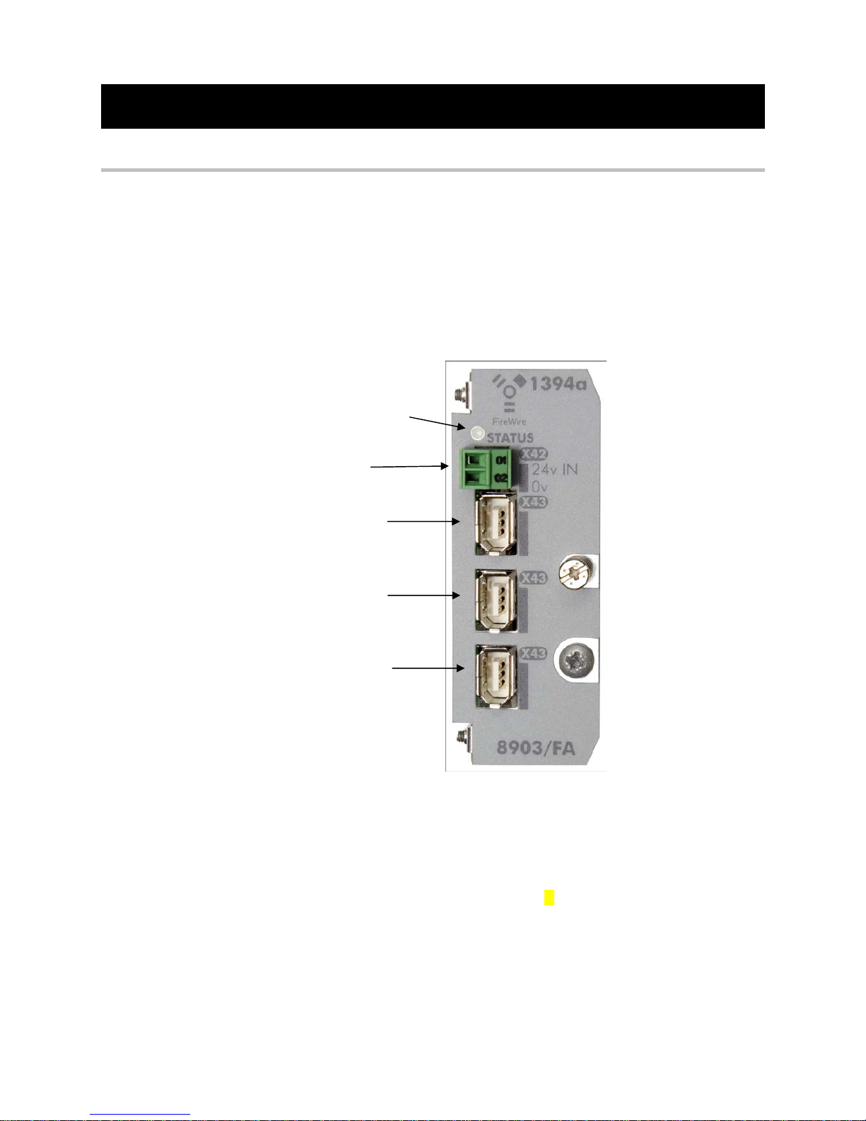
Figure 1. Front of the 8903/FA FireWire Communications Interface Option (Option)
STATUS LED
X42
POWER INPUT
CONNECTOR
X43
FIREWIRE PORT 0
X43
FIREWIRE PORT 1
X43
FIREWIRE PORT 2

2
8903/FA Firewire IEEE 1394a Communications Interface
WARNING!
Before installing, ensure that the drive
wiring is electrically isolated and cannot be
made “live” unintentionally by other
personnel. Wait 5 minutes after
disconnecting power before working on
any part of the system or removing the
covers from the drives.
Figure 2. 890 showing Control Board
withdrawn with Options fitted
2
1
1
Figure 3. Front of 890 drive showing
Control Board fitted
Legacy 890 drive without
the STO feature
2
Installation
To Remove the Control Board
1. Remove the blanking plates, each secured by a single
screw, that fits over the option slots (1).
2. Loosen the top and bottom screws from the handles
of the Control Board (2).
3. Pull gently on the handles and slide the Control
Board out of the drive.
Note:
Save the blanking plate and screw for future
use. The drive should not be operated without either
an option or blanking plate fitted. When fitted, these
maintain the drive's IP20 rating.
Caution
This Option contains ESD (Electrostatic
Discharge) sensitive parts. Observe static control
precautions when handling, installing and
servicing this Option.
3
8903/FA Firewire IEEE 1394a Communications Interface
Fitting the Option
The Option fits on to the Control Board.
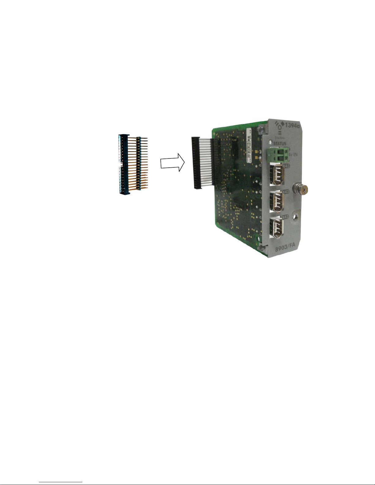
1. Insert the connector into the Option as shown. The legs of the connector will protrude
through into the connector on the other side of the Option.
2. Press the assembly into the BOTTOM connector (adjacent to terminals X13, X14 and X15)
on the Control Board. Ensure that the front panel of the Option overlaps the front of the
Control Board.
Figure 4. Fitting the connector to the Option
4
8903/FA Firewire IEEE 1394a Communications Interface
Re-fitting the Control Board
1. Slide the board into the drive, engaging the edges of the boards into the slots. Push until
the back edge of the Control Board PCB locates with the connectors in the drive.
2. Tighten in position using the top and bottom screws in the handles of the Control Board.
3. Screw the Option in position using the captive screw on the front of the Option.
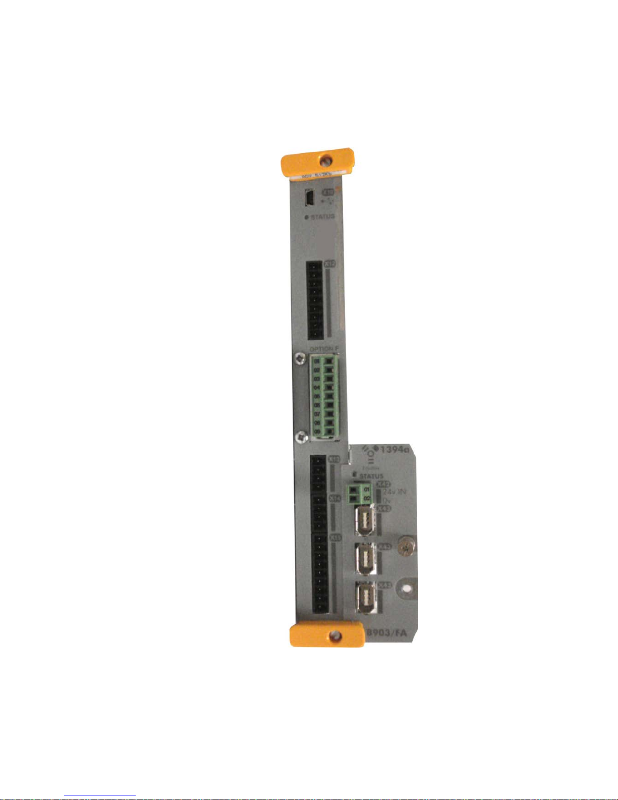
Figure 5. 890 Control Board with FireWire Communications Option fitted
Inhaltsverzeichnis
Andere Parker Aufnahmegeräte Handbücher


Beliebte Aufnahmegeräte Handbücher anderer Marken


Strymon
Strymon NIGHTSKY Bedienungsanleitung

Mitsubishi Electric
Mitsubishi Electric 16CH DIGITAL RECORDER DX-TL5000U Bedienungsanleitung

Tews Technologies
Tews Technologies TPMC465 Bedienungsanleitung

Honeywell
Honeywell Excel 50 Bedienungsanleitung

SeaLevel
SeaLevel COMM+8.LPCI Bedienungsanleitung

Arturia
Arturia AUDIOFUSE STUDIO Bedienungsanleitung


