
PAW K36E Bedienungsanleitung


1General Information
2 993x03x3x-mub-en –V01 2017/01
Contents
1General Information .............................................................................................................. 3
1.1 Scope of these instructions............................................................................................... 3
1.2 Designated use ................................................................................................................ 3
2Safety instructions ................................................................................................................ 4
3Product description ............................................................................................................... 5
3.1 Equipment ........................................................................................................................ 5
3.2 Function ........................................................................................................................... 6
3.3 Thermo controller ............................................................................................................. 8
3.4 Check valve.....................................................................................................................11
4Assembly and installation [specialist] ................................................................................... 12
4.1 Installation and commissioning of the HeatBloC ..............................................................12
4.2Accessories: Cutting-ring compression fitting (not included in the scope of delivery) .......15
5Scope of delivery [specialist] ............................................................................................... 15
5.1 Spare parts DN 25...........................................................................................................16
5.2 Spare parts DN 32...........................................................................................................17
6Technical data .................................................................................................................... 18
6.1 Pressure drop and pump characteristic curves DN 25 .....................................................19
6.2 Pressure drop and pump characteristic curves DN 32 .....................................................19
Item no. 993x03x3x-mub-en - Version V01 –Issued 2017/01
Translation of the original instructions
We reserve the right to make technical changes without notice!
Printed in Germany –Copyright by PAW GmbH & Co. KG
PAW GmbH & Co. KG
Böcklerstraße 11
D-31789 Hameln,
Germany
1General Information
2017/01 993x03x3x-mub-en –V01 3
1General Information
Carefully read these instructions before installation and commissioning.
Save these instructions in the vicinity of the installation for future reference.
1.1 Scope of these instructions
These instructions describe the installation, commissioning, function and the operation of the
HeatBloC K36E DN 25 and DN 32.
For other components of the installation, such as the pump, the controller or the modular
distribution manifold, please observe the instructions of the corresponding manufacturer.
The chapters called [specialist] are intended for specialists only.
1.2 Designated use
The HeatBloC may only be used in heating circuits taking into consideration the technical limit
values indicated in these instructions.
The HeatBloC must not be used in drinking water applications.
Improper usage of the HeatBloC excludes any liability claims.
This product complies with the relevant directives and is therefore labelled with the CE mark.
The Declaration of Conformity is available upon request, please contact the manufacturer.
Only use PAW accessories with the HeatBloC.
The wrapping materials are made of recyclable materials and can be disposed of with recyclable
materials.
2Safety instructions
4 993x03x3x-mub-en –V01 2017/01
2Safety instructions
The installation and commissioning as well as the connection of electrical components require
technical knowledge commensurate with a recognised vocational qualification as a fitter for
plumbing, heating and air conditioning technology, or a profession requiring a comparable level of
knowledge [specialist].
The following must be observed during installation and commissioning:
relevant local and national regulations
accident prevention regulations of the professional association
instructions and safety instructions of this manual
CAUTION
Personal injury and damage to property!
The HeatBloC must only be used in heating circuits filled with heating water
according to VDI 2035 / Ö-Norm H 5195-1.
The HeatBloC must not be used in drinking water applications.
NOTICE
Material damage due to mineral oils!
Mineral oil products cause lasting damage to seals made of EPDM, whereby the sealant
properties get lost. We do not assume liability nor provide warranty for damage to property
resulting from sealants damaged in this way.
It is imperative to avoid that EPDM gets in contact with substances containing mineral
oils.
Use a lubricant based on silicone or polyalkylene and free from mineral oils,
such as Unisilikon L250L and Syntheso Glep 1 of the Klüber company or a silicone
spray.
3Product description
2017/01 993x03x3x-mub-en –V01 5
3Product description
The HeatBloC K36E (boiler charging set) is a preassembled fitting group for hydronic heating
closed-loop systems.
The pump can be isolated by means of the ball valves and maintenance work on the pump can
thus be carried out without draining the boiler circuit.
You can mount the PAW HeatBloC directly onto a wall bracket or under/on a PAW modular
distribution manifold. With adaptor connections, PAW HeatBloCs can also be installed on
PAW distribution manifolds with other dimensions.
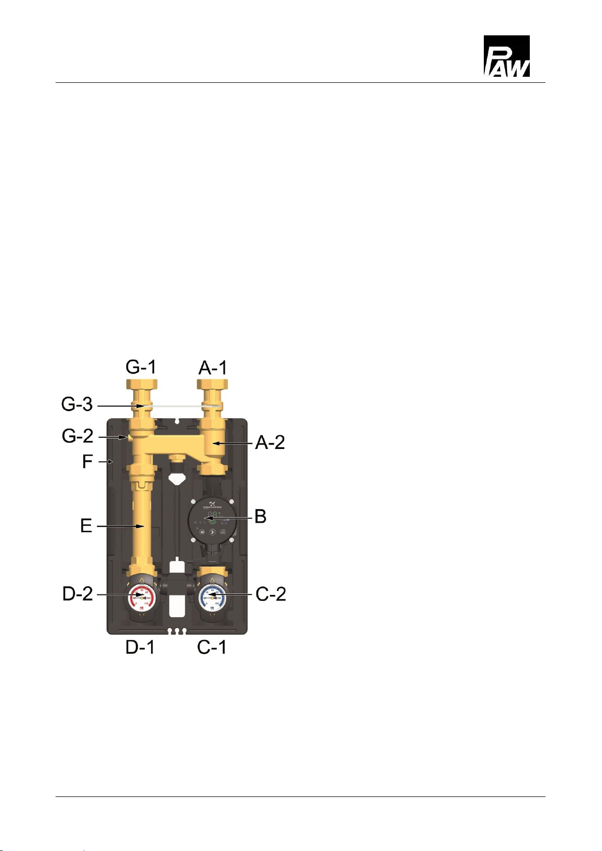
3.1 Equipment
A-1
Return from the consumer circuit
A-2
Thermo controller with
adjustable overflow valve
B
Heating pump
C-2
Full metal thermometer
integrated in the ball valve
(return, blue)
C-1
Return to the heat generator
D-1
Flow from the heat generator
D-2
Full metal thermometer integrated in
the ball valve (flow, red)
E
Flow pipe
F
Design insulation
with optimised function
G-2
Check valve, can be opened
G-3
Coupling piece for overhead
installation
G-1
Flow to the consumer circuit
3Product description
6 993x03x3x-mub-en –V01 2017/01
3.2 Function
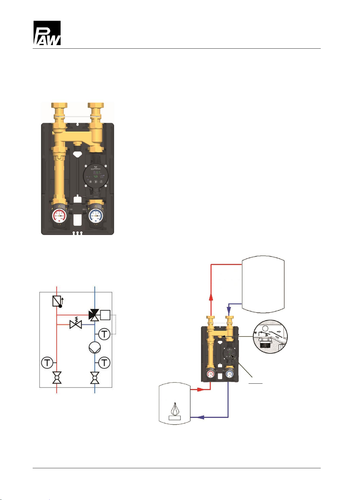
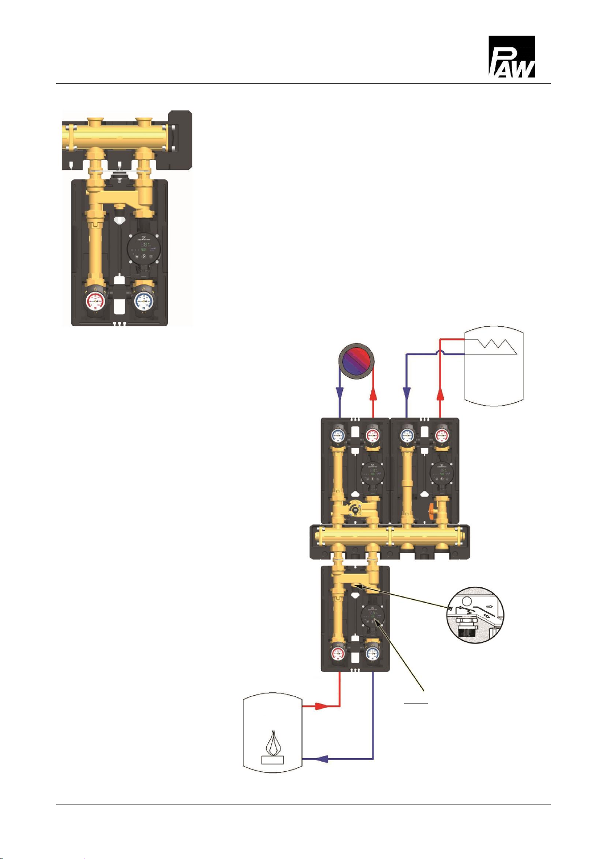
K36E boiler charging set for return flow temperature maintenance
of solid fuel boilers, wood firing and stove heating systems
The boiler charging set prevents the temperature in the boiler
from falling under the dew point, thus reducing the contamination
of the boiler.
Application ranges:
The boiler charging set can be mounted to a buffer tank or
to a hydraulic separator. If the opening temperature of
45 °C or 60 °C is reached in the boiler circuit, the
performance of the boiler can be used to charge the tank or
the hydraulic separator.
The following figure shows the adjustments necessary for this
system.
Buffer
tank
Solid fuel
boiler
Overflow valve closed
(adjustment knob screwed in)
Pump:
Operation mode: ∆p-c
Performance: maximum
3Product description
2017/01 993x03x3x-mub-en –V01 7
The boiler charging set can be mounted under/on a
distribution manifold. In this system the pump exerts a
pressure on the entire installation. When the overflow valve
in the thermo controller is open, the pressure can be
reduced via the valve. Undesired circulation, which could
lead to overcharging of the domestic water tank, can thus
be prevented.
The following figure shows the adjustments necessary for this
system.
Domestic water
tank
Overflow valve open
(adjustment knob screwed out)
Solid fuel
boiler
Pump:
Operation mode: ∆p-c
Performance: ²⁄₃ max. or speed level II
3Product description
8 993x03x3x-mub-en –V01 2017/01
3.3 Thermo controller
The thermo controller is equipped with an overflow valve and a thermal control valve.
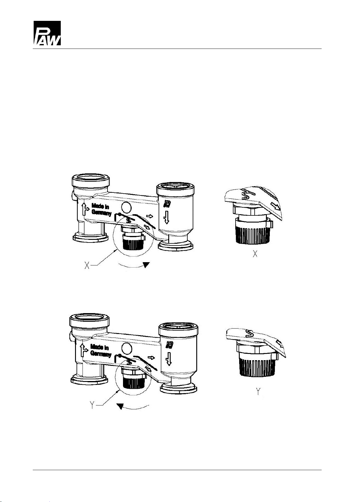
Overflow valve
In systems with a distribution manifold, the pump of the boiler charging set exerts an initial
pressure on the entire installation. If the overflow valve of the thermo controller is open,
the pressure can be reduced via the valve. Undesired circulation, which could lead to an
overcharging of the domestic hot water tank, can thus be prevented.
Overflow valve open
close
Overflow valve closed
open
3Product description
2017/01 993x03x3x-mub-en –V01 9
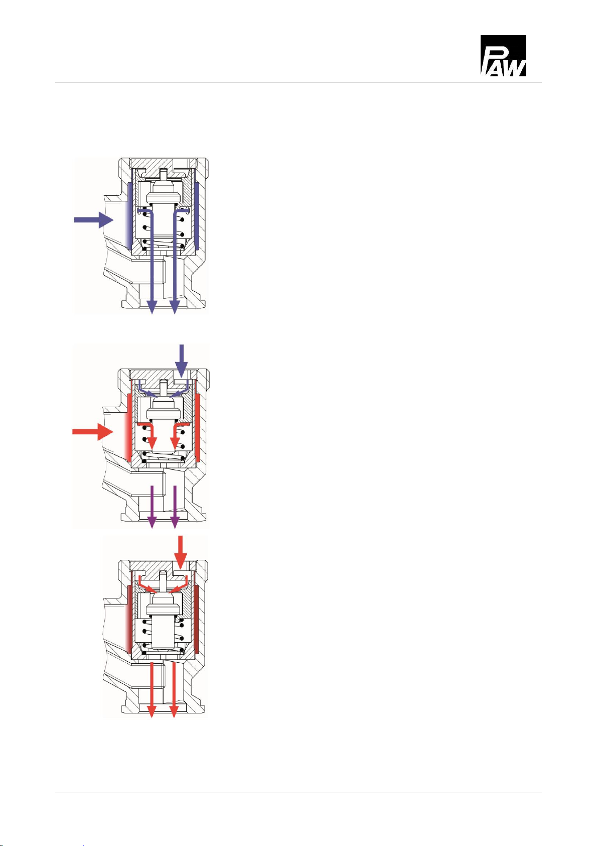
Thermal control valve
The thermal control valve serves as a bypass in the startup phase.
1. If the water temperature in the boiler circuit is lower than
the opening temperature of the thermal control valve,
this valve is closed and thus also the line to the
consumers. The water circulates in the boiler circuit via
the completely open bypass.
2. As soon as the water in the boiler circuit has reached the
opening temperature (+/- 3 K), the thermal control valve
starts opening the line from/to the consumers.
This enables the circulation in the consumer circuit.
The cold water from the consumer return line is mixed
with the hot water from the bypass at the control valve.
Depending on the temperature and the flow rate of the
water from the return line, the thermal control valve shuts
or opens the line to the consumers. Thus, the return to
the boiler always remains at a certain temperature level.
3. With increasing temperature in the return line of the
consumers, the thermal control valve completely opens
the line to the consumers. During operation, the
temperature of the return of the boiler remains nearly
constant (+/ -3 K) until the buffer tank is completely
charged.

3Product description
10 993x03x3x-mub-en –V01 2017/01
Change of the flow line [specialist]
1. Take off the thermometer handles (C-2, D-2)
and remove the insulating front shells.
2. Take the group of fittings out of the insulating
back shell.
3. Loosen the union nuts at the thermo controller
(A-2).
4. Dismount the thermo controller and turn it by
180° around the vertical axis.
Retrofitting and commissioning of the heating circuit
1. Interchange the flow line with the return line and
the pump (B).
2. Re-install the thermo controller and tighten the
union nuts.
Consider the flow direction of the pump!
Turn the pump head such that the terminal box is
directed to the top or to the centre of the group of
fittings.
3. Mount the HeatBloC and connect it to the
installation.
4. Check all union nuts before commissioning and
firmly tighten them if necessary.
5. Mount the insulation only after having carried
out a pressure test.
Mount the thermometer handles (C-2, D-2) in a
final step.
Andere Handbücher für K36E
2
Dieses Handbuch passt für folgende Modelle
2
Inhaltsverzeichnis


