
Pego ECP200 Expert d7.5 Bedienungsanleitung
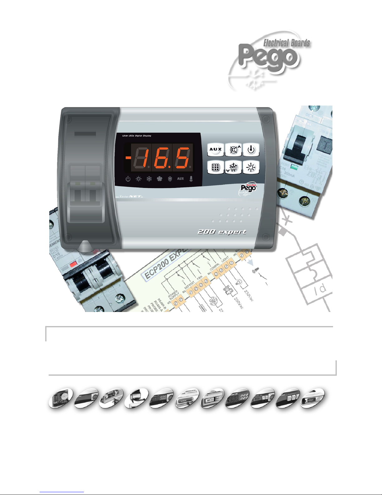
ECP 200 EXPERT
USE AND MAINTENANCE MANUAL
REV. 04-06

ECP200 EXPERT

ECP200 EXPERT
Pag. 3
USE AND MAINTENANCE MANUAL
Rev. 04-06
INTRODUCTION
Page 4 1.1 General
Page 4 1.2 Product ID codes
Page 5 1.3 Overall dimensions
Page 5 1.4 Identification data
INSTALLATION
Page 6 2.1 Important information for the installer
Page 6 2.2 Standard assembly kit
Page 7 2.3 Installing the unit
FUNCTIONS
Page 9 3.1 ECP200 EXPERT panel functions
TECHNICAL CHARACTERISTICS
Page 10 4.1 Technical characteristics
Page 11 4.2 Warranty
PARAMETER PROGRAMMING
Page 11 5.1 Control panel
Page 11 5.2 Frontal keypad
Page 12 5.3 LED display
Page 13 5.4 General
Page 13 5.5 Key to symbols
Page 13 5.6 Setting and displaying set points
Page 14 5.7 Level 1 programming
Page 15 5.8 List of Level 1 variables
Page 16 5.9 Level 2 programming
Page 16 5.10 List of Level 2 variables
Page 18 5.11 Switching on the ECP200 BASE electronic controller
Page 18 5.12 Compressor activation/deactivation conditions
Page 19 5.13 Manual defrosting
Page 19 5.14 Hot gas defrosting
Page 19 5.15 Pump down function
OPTIONAL
Page 21 6.1 TeleWIN- TeleNET monitoring / supervision system
Page 22 6.2 ALARM RELAY /TeleWIN- TeleNET switching
TROUBLESHOOTING
Page 23 7.1 Troubleshooting
ALLEGATI / APPENDICES
Page 24 A.1 EC declaration of conformity
Page 25 A.2 ECP200 EXPERT wiring diagram
Page 26 A.3 TeleWIN – TeleNET network connection diagram
Page 27 A.4 Part list
CONTENTS
CHAP. 1
CHAP. 2
CHAP. 3
CHAP. 4
CHAP. 5
CHAP. 6
CHAP. 7

ECP200 EXPERT
Pag. 4 USE AND MAINTENANCE MANUAL
Rev. 04-06
GENERAL
DESCRIPTION:
The ECP200 EXPERT is a new control panel for cold rooms with a single-phase
compressor up to 2 HP, specially designed to provide the user with safety, protection,
control and ease of installation.
It allows the user to control all the components on a refrigerating system: compressor,
evaporator fans, defrosting elements, room light and thermostat-holder demisting element.
APPLICATIONS:
- Complete management of single-phase static or ventilated refrigeration systems up
to 2 HP, with off-cycle or electrical defrosting and with direct or pump-down
compressor stop.
- Control of single-phase evaporator unit only with freon solenoid consensus or
remote condensing unit consensus.
MAIN CHARACTERISTICS:
- Direct control of defrosting elements, evaporator fans, room light with outputs
directly connectable to the various units.
- Magneto-thermal cut-out switch for isolation and protection of the refrigeration unit.
- Innovative, smartly designed ABS cover with transparent cover for access to the
magneto-thermal cut-out switch, all with an IP65 protection rating so that panel can
be used outside the room.
- LED indicators and large display illustrate system status.
- User-friendly keypad.
- Auxiliary relay with parameter-configured activation (alarms, temperature set point,
direct control via front push-button, thermostat-holder demisting element, remote
condensing unit consensus, freon solenoid control in the event of compressor
pump-down operation).
- Possibility, as an alternative to an auxiliary relay, of a RS485 port for connection to
the TeleWIN supervision network (industrial TeleNET for local networks without
instrument limits).
- Temperature control to 0.1 °C.
PRODUCT ID CODES
ECP200 EXPERT controls and manages compressor,
defrosting elements, evaporator fans and
room light. Aux/Alarms relay
1.1
1.2
CHAPTER 1: INTRODUCTION
CHAP. 1 - Introduction
ECP200 EXPERT
Pag. 5
USE AND MAINTENANCE MANUAL
Rev. 04-06
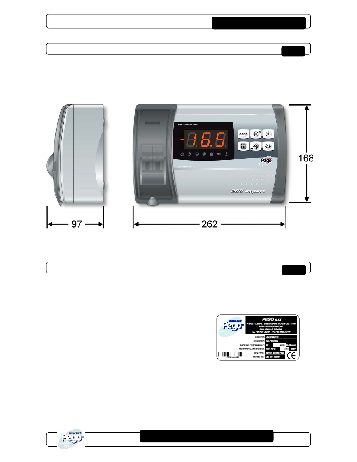
OVERALL DIMENSIONS
Dimensions (mm.)
IDENTIFICATION DATA
The unit described in this manual has an ID plate on the side showing all the relevant
identification data:
• Name of Manufacturer
• Code and model of unit electrical board
• Serial number
• IP protection rating
• Power supply
1.3
1.4
CHAP. 1 - Introduction
ECP200 EXPERT
Pag. 6 USE AND MAINTENANCE MANUAL
Rev. 04-06
IMPORTANT INFORMATION FOR THE INSTALLER
1. Install the device in places where the protection rating is observed and try not to
damage the box when drilling holes for wire/pipe seats.
2. Do not use multi-polar cables in which there are wires connected to inductive/power
loads or signalling wires (e.g. probes/sensors and digital inputs).
3. Do not fit power supply wiring and signal wiring (probes/sensors and digital inputs) in
the same raceways or ducts.
4. Minimise the length of connector wires so that wiring does not twist into a spiral shape
as this could have negative effects on the electronics.
5. Fit a general protection fuse upstream from the electronic controller.
6. All wiring must be of a cross-section suitable for relevant power levels.
7. When it is necessary to make a probe/sensor extension, the wires must have a cross-
section of at least 1 mm2.
STANDARD ASSEMBLY KIT
For the purposes of assembly and use, the electronic ECP200 EXPERT control unit
comes with:
• N° 3 seals, to be fitted between the fixing screws and the box back panel
• N° 1 user’s manual.
CHAPTER 2: INSTALLATION
CHAP. 2 - Installation
2.1
2.2

ECP200 EXPERT
Pag. 7
USE AND MAINTENANCE MANUAL
Rev. 04-06
INSTALLING THE UNIT
Fig. 1: Raise the transparent cover
that shields the magneto-thermal
cut-out switch and remove the
screw cover on the right-hand
side.
Fig. 2: Undo the 4 fixing screws at the
front of the box.
Fig. 3: Close the transparent cut-out switch
cover.
Fig. 4: Open the front of the box, lift it and
slide the two hinges out as far as
they will go.
Fig. 5: Press on the sides of the hinges to
remove them from their seats and so
remove the front panel completely.
CHAP. 2 - Installation
2.3

ECP200 EXPERT
Pag. 8 USE AND MAINTENANCE MANUAL
Rev. 04-06
(
((
Fig. 6: Use the three existing holes to fix the
box back panel to the wall: use three
screws of a length suitable for the
thickness of the wall to which the
panel will be attached. Fit a rubber
washer (supplied) between each
screw and the box backing.
Fig. 7: Hook the frontal panel back up to the
lower part of the box by inserting the
two hinges in their seats and, bending
them, rotate downwards 180° to gain
access to the electronic board.
Make all the electrical connections as illustrated in the diagram for the corresponding
model (see relative table in APPENDICES).
To effect correct electrical connection and maintain the protection rating, use
appropriate wire/raceway grips to ensure a good seal.
Route the wiring inside the unit in as tidy a fashion as possible: be especially careful to keep power
wires away from signal wires. Use clips to hold wires in place.
Fig. 8: close the front panel, making sure
that all the wires are inside the box
and that the box seal sits in its seat
properly.
Tighten the front panel using the 4
screws, making sure the O-rings on
the head of each screw are used.
Power up the panel and carry out
thorough reading/programming of all
the parameters.
Be careful not to over-tighten the closure screws as this could warp the box and
compromise proper operation of the membrane-type keypad.
Install short-circuit overload safety devices on all the power cables connected to the
ECP200 EXPERT so as to prevent damage to the device. Work and/or maintenance
must ONLY be carried out on the unit after disconnecting the panel from the power supply and
from any inductive/power loads: doing so allows the worker to do his job safely.
CHAP. 2 - Installation

ECP200 EXPERT
Pag. 9
USE AND MAINTENANCE MANUAL
Rev. 04-06
ECP200 EXPERT PANEL FUNCTIONS
- Display and adjustment of cold room temperature accurate to 0.1 °C.
- Display of evaporator temperature from parameter
- System control activation/deactivation
- System warnings (probe/sensor errors, minimum and maximum temperature warnings,
compressor shutdown)
- Evaporator fans control
- Automatic and manual defrost (static, heating element, cycle inversion)
- Direct control of compressor unit up to 2 HP
- Room light, via panel key or door switch
- Alarms/auxiliary relay
CHAPTER 3: FUNCTIONS
3
.1
CHAP. 3 - Functions
ECP200 EXPERT
Pag. 10 USE AND MAINTENANCE MANUAL
Rev. 04-06
TECHNICAL CHARACTERISTICS
Power supply
Voltage 230 V~ ±10% 50Hz / 60Hz
Max power (only electronics) ~ 7 VA
Cold room conditions
Working temperature -5 ÷ 50°C
Storage temperature -10 ÷ 70°C
Relative humidity Less than 90%
General characteristics
Type of sensors that can be connected NTC 10K 1%
Resolution 0,1 °C.
Sensor read precision ± 0,5 °C
Read range -45…+45 °C
ECP200 EXPERT - Output characteristics - max applicable load (230 V AC)
Compressor 1500W (AC3)
Elements 3000W (AC1)
Fans 500W (AC3)
Room light 800W (AC1)
Alarm contact (non-powered contact) 100W
General electrical protection Magneto-thermal cut-out switch
Bi-polar 16A Id=300 mA
Disconnecting power 4.5 kA
Dimensional characteristics
Dimensions 16.8 cm x 9.7 cm x 26.2 cm (HxPxL)
Insulation / mechanical characteristics
Box protection rating IP65
Box material Self-extinguishing ABS
Type of insulation Classe II
CHAP. 4 - Technical characteristics
CHAPTER 4: TECHNICAL CHARACTERISTICS
4.1
Andere Handbücher für ECP200 Expert d7.5
8
Inhaltsverzeichnis
Andere Pego Controller Handbücher

Pego
Pego Vision Touch Wellness Betriebsanleitung

Pego
Pego 200NDIN3RK Betriebsanleitung

Pego
Pego PLUS 100 AB Bedienungsanleitung

Pego
Pego ECP200 Expert d7.5 Bedienungsanleitung

Pego
Pego ECP200 BASE Series Bedienungsanleitung

Pego
Pego VISION SC600 Bedienungsanleitung

Pego
Pego 200PEVS01 Betriebsanleitung

Pego
Pego 200NDINFSC Betriebsanleitung

Pego
Pego ECP200 Expert d7.5 Bedienungsanleitung

Pego
Pego EasySteam 400HUM2ESXX Bedienungsanleitung


