
power automation PA 8000 EL Bedienungsanleitung
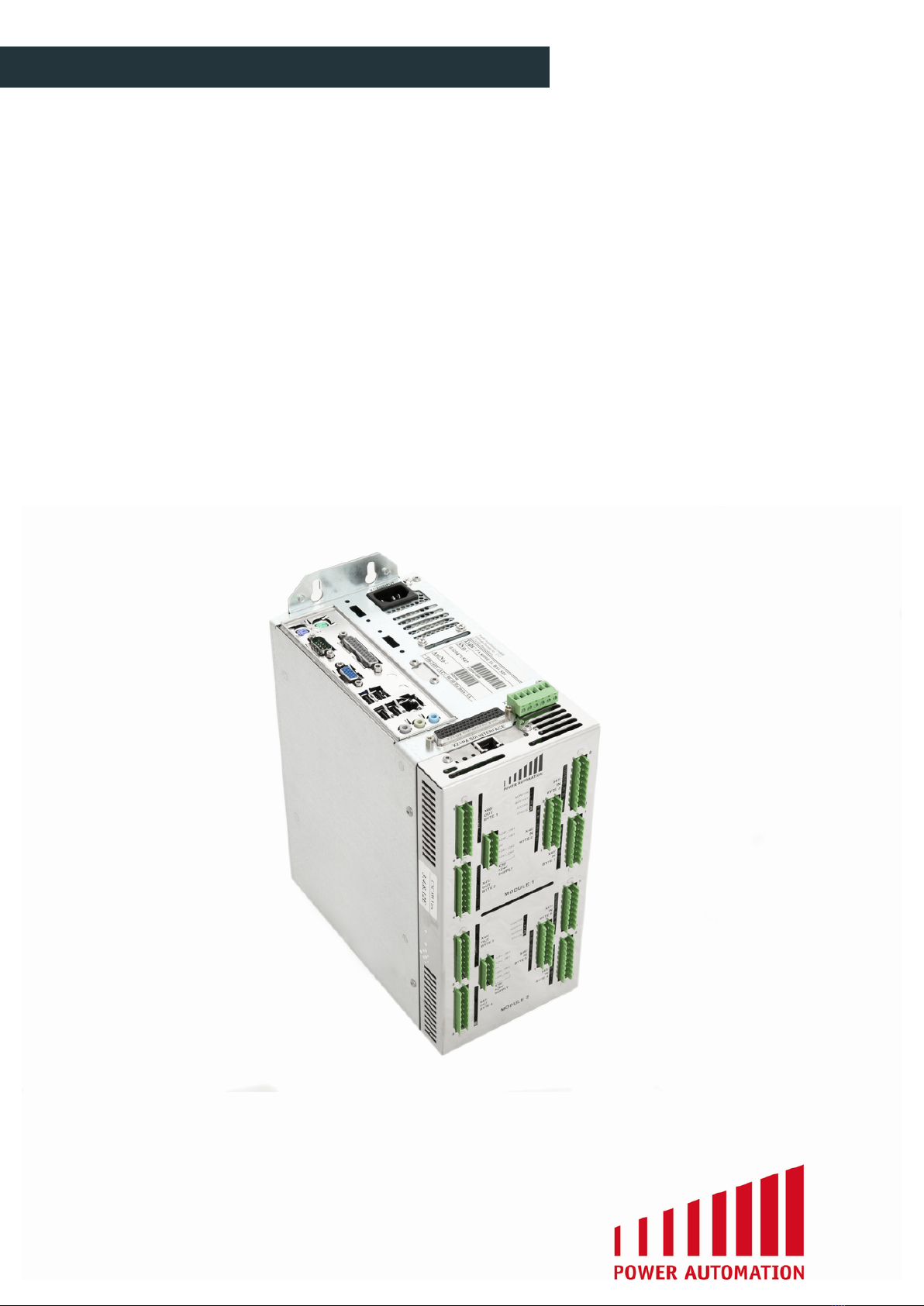
PA 8000 EL
CNC control unit
Installation instructions

Option: PA 8000 EL PRO-SDI / PA 8000E EL PRO-SDI
Original installation instructions
©2015 Power Automation GmbH
Power Automation GmbH
CNC-Automatisierungstechnik
Gottlieb-Daimler-Str. 17/2
74385 Pleidelsheim
Germany
Telephone: +49-7144-899-0
Fax: +49-7144-899-299
email: [email protected]
Internet: www.powerautomation.com
Version 2.0
2 24.09.2015

Table of contents
1 General information............................................................. 7
1.1 Information on this manual.......................................... 7
1.2 Explanation of symbols................................................ 7
1.3 Limitation of liability...................................................... 9
1.4 Copyright..................................................................... 9
1.5 Warranty terms............................................................ 9
1.6 Customer service....................................................... 10
1.7 Glossary..................................................................... 10
2 Safety.................................................................................. 11
2.1 Customer's responsibility........................................... 11
2.2 Personnel requirements............................................. 12
2.2.1 Qualifications........................................................... 12
2.2.2 Unauthorized persons............................................. 12
2.3 Intended use.............................................................. 13
2.4 Unintended use.......................................................... 14
2.5 Personal protective gear............................................ 14
2.6 Specific dangers........................................................ 15
2.7 Safety devices........................................................... 17
2.8 Machine safety........................................................... 17
2.8.1 'CNC ready' signal - Emergency stop interlocking.. 18
2.8.2 'Power ok' signal..................................................... 19
2.9 Conduct in a dangerous situation and in case of
accidents.................................................................... 19
2.10 Data safety................................................................. 20
2.10.1 File backup.............................................................. 20
2.10.2 System protection................................................... 20
2.11 Environmental protection........................................... 22
2.12 Labels........................................................................ 23
3 Design and function.......................................................... 27
3.1 Overview.................................................................... 27
3.2 Brief description......................................................... 27
3.3 Module 2416 EL......................................................... 28
3.3.1 Digital inputs............................................................ 29
3.3.1.1 Input interfaces..................................................... 29
3.3.1.2 Input characteristics.............................................. 33
3.3.1.3 Input schematic.................................................... 34
PA 8000 EL CNC control unit
Table of contents
24.09.2015 | 3

3.3.1.4 Handwheel I/O...................................................... 34
3.3.2 Digital outputs......................................................... 37
3.3.2.1 Output interfaces.................................................. 37
3.3.2.2 Output characteristics........................................... 41
3.3.2.3 Output schematic.................................................. 42
3.3.3 Power connection.................................................... 43
3.3.4 Module 2416 EL LEDs............................................ 46
3.4 SDI interface.............................................................. 47
3.5 PC connectors........................................................... 49
3.6 Safety connector........................................................ 55
3.6.1 Safety connector specification................................ 56
3.6.2 Safety connector schematic.................................... 59
3.7 (X20) PA USB software dongle connector................. 59
3.8 PAMIO interface (superbus)...................................... 60
3.8.1 PAMIO boxes and modules.................................... 61
4 Technical data.................................................................... 65
4.1 General specifications............................................... 65
4.2 Connection values..................................................... 65
4.3 Operating conditions.................................................. 66
4.4 Dimension sheet........................................................ 67
4.5 Electromagnetic compatibility.................................... 68
4.6 Installation guidelines................................................ 69
5 Installation.......................................................................... 73
5.1 Prerequisites and preparations.................................. 73
5.1.1 General requirements............................................. 73
5.1.2 Electrical cabinet structural requirements............... 74
5.1.3 Cabinet temperature............................................... 74
5.2 Mounting the control unit in a cabinet........................ 75
5.3 Installing digital I/O.................................................... 80
5.3.1 Wiring example for 2416EL modules...................... 80
5.4 Wiring for machine safety.......................................... 81
5.4.1 Wiring example for 'CNC ready' relay..................... 82
5.4.2 Wiring example for 'Power ok' relay........................ 83
6 Transport, packaging and storage................................... 85
6.1 Transport................................................................... 85
6.2 Packaging.................................................................. 85
6.3 Storage...................................................................... 86
PA 8000 EL CNC control unit
Table of contents
24.09.2015 | 4

7 Maintenance....................................................................... 87
7.1 Safety notes............................................................... 87
7.2 Maintenance schedule............................................... 87
7.3 Measures after maintenance..................................... 88
8 Troubleshooting................................................................. 89
8.1 Safety notes............................................................... 89
8.2 Malfunction indicators................................................ 90
8.2.1 Module 2416 EL LEDs............................................ 91
8.3 Troubleshooting chart................................................ 93
9 Service and return process............................................... 95
9.1 Service....................................................................... 95
9.1.1 Service addresses................................................... 95
9.2 Spare parts................................................................ 97
9.3 Return policy and procedure...................................... 97
9.4 Training.................................................................... 100
10 Dismounting and decommissioning.............................. 101
11 EC Declaration of Conformity......................................... 103
12 Proof of change................................................................ 105
13 Index.................................................................................. 107
PA 8000 EL CNC control unit
Table of contents
24.09.2015 | 5

PA 8000 EL CNC control unit
Table of contents
24.09.2015 | 6
1 General information
1.1 Information on this manual
This installation manual provides important information on how to
work with the control unit safely and efficiently.
The installation manual is part of the control unit, must always be
kept in the control unit's direct proximity and should be available for
the personnel at any time. All personnel working with the control
unit are obliged to have read and understood this installation
manual before starting any work. Strict compliance with all speci-
fied safety notes and instructions is a basic requirement for safety
at work.
Moreover, the accident prevention guidelines and general safety
regulations applicable at the place of use of the control unit must
also be complied with.
Illustrations in this installation manual are intended to facilitate
basic understanding, and may differ from the actual design of the
control unit.
The enclosed manuals for the installed components apply together
with this installation manual.
1.2 Explanation of symbols
Warnings are identified by pictures. These warnings are introduced
by signal words, which express the severity of a danger.
Pay attention to these warnings and act cautiously in order to avoid
accidents, personal injuries and damage to property.
DANGER!
… indicates an imminently hazardous situation which,
if unavoidable, will result in death or serious injury.
WARNING!
… indicates a potentially hazardous situation which, if
unavoidable, could result in death or serious injury.
CAUTION!
… indicates a potentially hazardous situation which, if
unavoidable, may result in minor or moderate injury.
NOTICE!
… indicates a potentially hazardous situation which, if
unavoidable, may result in property damage.
General Information
Warnings
PA 8000 EL CNC control unit
General information
24.09.2015 | 7
… emphasizes useful hints and recommendations as
well as information for efficient and trouble-free opera-
tion.
The following symbols are used in connection with the safety notes
to highlight particular dangers:
DANGER!
… highlights hazards caused by electric current. There
is a danger of serious injury or death if the safety notes
are not complied with.
The following symbols and highlights are used to distinguish
instructions, descriptions of results, cross-references and other ele-
ments inside this manual.
.. Highlights a step as part of a procedure of instructions.
ð.. Highlights a state or an automatic process as a result of
an instruction.
n.. Highlights single or unordered instructions and lists.
Ä
“Additional symbols and highlighting” on page 8.. Highlights
cross-references to chapters or sections of this manual.
[Key].. Highlights captions of buttons, fields and other elements of
the software's graphical user interface.
“Menu è Submenu è ”.. Highlights a path to access a menu or
submenu in the software's graphical user interface.
Example/Extract.. Highlights verbatim examples and extracts
from configuration files.
Special Safety Notes
Additional symbols and high-
lighting
PA 8000 EL CNC control unit
General information
24.09.2015 | 8

1.3 Limitation of liability
All information and notes in this installation manual were compiled
under due consideration of valid standards and regulations, the
present status of technology and our years of knowledge and
experience.
Power Automation can not be held liable for damage resulting
from:
ndisregarding this installation manual
nunintended use
nemployment of untrained personnel
nunauthorized conversions
nunauthorized modifications to the software
ntechnical modifications
nuse of unapproved spare parts
nuse in conjunction with machines not deemed compatible by
Power Automation
In case of customized versions the actual scope of delivery can
vary from the explanations and representations in this installation
manual, because of the utilization of additional options or due to
the latest technical changes.
Apart from this, the obligations agreed upon in the delivery con-
tract, the general terms and conditions, and the delivery conditions
of Power Automation and the legal regulations valid at the time of
contract apply.
We reserve the right to make technical modifications in order to
improve usability.
1.4 Copyright
This installation manual is protected by copyright law.
Passing this installation manual on to third parties, duplication of
any kind – even in form of excerpts – as well as the use and/or dis-
closure of the contents without the written consent of Power Auto-
mation is not permitted.
Violations oblige to compensation. The right for further claims
remains reserved.
1.5 Warranty terms
The material warranty terms are provided in Power Automation's
terms and conditions as well as inside the sales documents.
Liability
Copyright
Material Warranty
PA 8000 EL CNC control unit
General information
24.09.2015 | 9

1.6 Customer service
Our Customer Service is always available for technical information.
For information on whom to contact by phone, fax, e-mail or via the
internet, see Power Automation's address on page 2.
Additionally, Power Automation staff is always interested in
receiving new information and experiences resulting from the use
of our products, which could be of great value for future improve-
ments.
1.7 Glossary
CMOS - Complementary metal-oxide-semiconductor
CNC - Computerized Numerical Control
DDU - Delivered Duty Unpaid
HMI - Human Machine Interface
The graphical user interface provided by the PA soft-
ware.
IPC - Insulating Piercing Connector
MDI - Manual Data Input
MTBP - Machine Tool Builder's Panel
Panel including the basic requirements for a machine
tool operator: emergency stop push button, cycle start
and stop push buttons, jog plus and minus push but-
tons, feed rate and spindle speed override pots and a
number of auxiliary push buttons.
NC-Start - Numerical Control Start Button
NC-Stop - Numerical Control Stop Button
PA - Power Automation
PAMIO - Power Automation Modular Input Output
Extendable Superbus based interface allowing
connection of additional I/O modules.
PASIO - Power Automation Slot Input Output
Extendable EtherCATâ based interface allowing
connection of additional I/O modules.
PC - Personal Computer
PCI - Peripheral Component Interconnect
Personal computer extension for periphery devices
connected to the motherboard.
PLC - Programmable Logic Controller
POU - Program Organization Unit PLC functions, function
blocks and programs are POUs
RMS - Rotating Measuring Systems (Encoder)
Service
PA 8000 EL CNC control unit
General information
24.09.2015 | 10
Dieses Handbuch passt für folgende Modelle
4
Inhaltsverzeichnis
Andere power automation Steuereinheit Handbücher


Beliebte Steuereinheit Handbücher anderer Marken

Festo
Festo Compact Performance CP-FB6-E Stücklistenhandbuch

Elo TouchSystems
Elo TouchSystems DMS-SA19P-EXTME Bedienungsanleitung

JS Automation
JS Automation MPC3034A Bedienungsanleitung

JAUDT
JAUDT SW GII 6406 Series Kurzanleitung

Spektrum
Spektrum Air Module System Bedienungsanleitung

BOC Edwards
BOC Edwards Q Series Bedienungsanleitung


