PPA AGILITY PLUS Betriebsanleitung

AGILITY PLUS BOARD
PROGRAMMING GUIDE
ALARM FUNCTION
WARNING
Do not use the equipment without rst
reading the instruction manual.
PXXXXX - 05/2022
Rev. 1

2
MAIN FEATURES OF THE ALARM FUNCTION
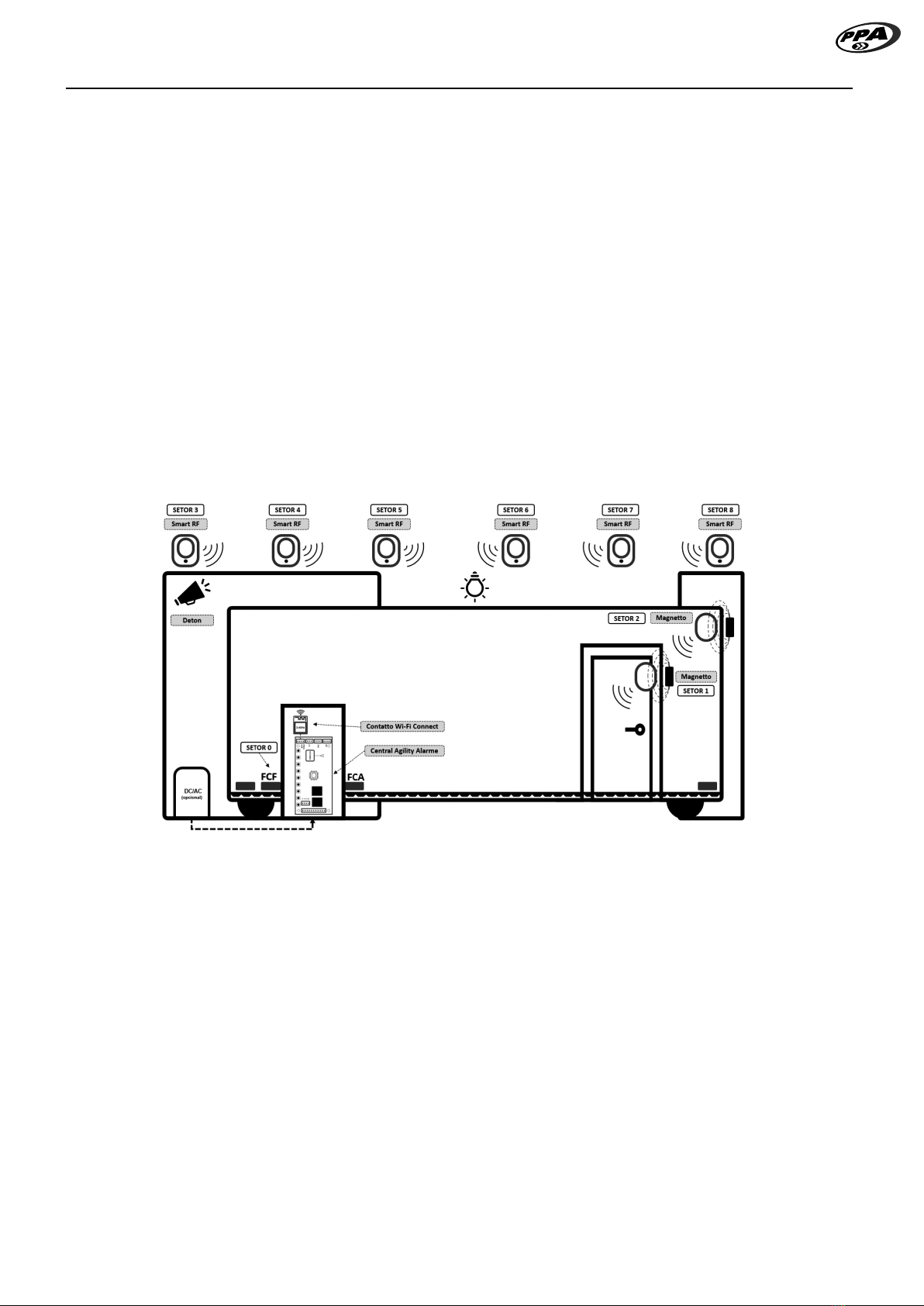
• 1 Wired Sector [Closing limit switch – FCF]
• 8 Wireless Sectors 433.92MHz [ Magnetto / Smart RF ]
• Selection of ZAP4 transmitter button as Arm / Disarm function
• Selection of ZAP4 transmitter button as Internal Arming function
• Replacement or exchange of the defective sector’s wireless device without the need to delete and re-record
all sectors.
• Siren time [1 minute to 240 minutes]
• Auto-arm exit time [1 second to 240 seconds]
• Latch output as PGM module programmable output [ Siren, Hold, Pulsed, 1 Pulse, 2 Pulses, 3 Pulses and
Remote control wri ]
• Individual programming for each sector:
- Sector ON / OFF
- Shooting Mode (Inant or Timed [1 second up to 240 seconds])
- Auto-Cancellable Counter (OFF, Number of Events [1 to 250])
- Auto Override Mode (Siren Trigger or Sensor Trigger)
- Internal Arming (ON, OFF)
• Enable / Disable armed warning beep silent mode when gate is closed, as follows:
- Garage Light Only
- Garage Light + Siren
- Siren only
• Configurable Panic Button Function:
- Enable / Disable
- Selection of the panic button on the control
- Access buttons
- Button #1, Button #2, Button #3 or Button #4
- Setting the time for triggering the panic alarm [30sec to 10min]
- Enable / Disable panic alarm silent mode
- WiFi only
- Siren only
- WiFi + Siren
- Panic key action
- Pulse2=Only Secure Access1
- Pulse=Siren On/Off and Time 3seg=Secure Access
- Pulse=Secure Access and Time 3sec3= Siren On/Off
- Monitoring and Resetting of panic functions.
• Communication interface with the Contatto Wi-Fi Connect device
• Schedules performed by PROG
• Verification of the operating conditions of the alarm, sectors and panic through the PROG display
Notes:
1When the gate is closed and the board receives a signal from the control where the button has a panic function, it will simultaneously trigger the panic timer and trigger
the gate to open, arting the Safe Access cycle. It is important to remember that the user-defined panic delay time value mu be greater than the time to complete the gate
opening/closing cycle, otherwise it will trigger the panic signal before completing the gate closing cycle.
2 The board recognizes and treats the control’s panic button as Pulse when this button is pressed and released from the control between the times of 0.5sec and 3sec.
3 The board recognizes and treats the control’s panic button as Tempo 3sec when this button is pressed and held on the control above the 3sec time.

3
APPLICATION
Figure 1 illurates a typical application of the Agility Plus Board acting as a gate alarm function.
It is intended for the perimeter protection of a garage and entrance gate. The magnet and reed sensor limit
switch besides setting the close limit also behaves as a wired sector of the alarm.
The social door of the gate can be monitored by the board when the Magnetto magnetic sensor is inalled
as a wireless sector.
If necessary, the Magnetto magnetic sensor can be inalled on the frame and on the gate for protection
again break-ins and tampering as a wireless sector.
Smart RF wireless infrared sensors can be inalled to protect indoor area such as garage area, residential
doors and windows as additional wireless sectors.
The latch output (TRV) behaves as a programmable PGM output for activating the Deton siren.
The garage light output (LG) has additional flash signaling functions to inform alarm activities such as arming
and disarming.
It has connectivity with the Contatto Wi-Fi Connect accessory for sending atus and receiving remote
command by application.
Figure 1 - Application of perimeter protection for the garage and gate

4
FUNCTIONING
In the factory default, only the wired sector, ie, the closing limit switch (FCF) is enabled for monitoring the gate
as specified in the table and its parameters.
Wireless sectors (sectors 1 through 8) are disabled by factory default.
When the board is energized and the gate is closed with the closing limit switch (FCF) activated or when the
gate closing cycle ends with the closing limit switch (FCF) sensor activated and the gate alarm function is
enabled the alarm will be armed after auto-arm time is reached. After arming the board, the garage light and
the PGM output (PGM TRV MODE selected as Siren) will be activated for a time of 0.5 seconds only once. for
5 sec and off for 1 sec.
To disarm the alarm, it will be necessary that the gate is closed with the limit switch sensor activated by the
gate magnet and also that the activated button of the transmitter is configured as Arm / Disarm. After the
board recognizes and validates the button as Arm / Disarm the alarm will be disarmed and the garage light
and PGM output (PGM TRV MODE selected as Siren) will activate for a time of 0.5 seconds repeated twice.
To arm the alarm, it will be necessary that the gate is closed with the limit switch sensor activated by the gate
magnet and also that the activated button of the transmitter is configured as Arm / Trip. After the board re-
cognizes and validates the button as Arm / Disarm, the alarm will be armed and the light The garage door and
the PGM output (PGM TRV MODE selected as Siren) will be activated for a time of 0.5 seconds once.
When the board receives an opening command with the valid access button, the opening cycle is arted and
the alarm is temporarily disarmed until the gate ends the closing cycle with the closing limit switch sensor ac-
tivated by the magnet. After the closing cycle, the arming time arts and when completed will arm the alarm
again. The garage light and the PGM output (PGM TRV MODE selected as Siren) will be activated for a time
of 0.5 seconds once.
With the gate closed and the alarm in the armed ate and if there is a violation or theft of the gate in which
the magnet moves away from the closing limit switch sensor or if the devices in the wireless sectors send the
radio frequency signal to the board that will go into an alarm ate where it will trigger the output PGM (TRV).
To cancel the gate alarm atus it will be necessary to command a valid gate opening button.
NOTE: For programming the alarm features it will be allowed if the gate is open.

5
VIEWING THE ALARM OPERATING CONDITIONS AND SECTORS THROUGH THE PROG
DISPLAY
To view the operating conditions of the alarm, sectors and the panic function, it will be necessary to be on the
main screen and then press the (-) key to change the monitoring as shown in the cycle shown below. It arts
at screen #1 and ends at screen #14, then returns to screen #1 repeating the cycle of display while the (-) key
is in use.
Figure 2 – Cycle of alarm, sectors and panic atus monitoring screens, monitoring whether alarm is enabled / disabled and times for
auto-arm and siren triggered.
Screen 1 Screen 8
Screen 2 Screen 9
Screen 3 Screen 10
Screen 4 Screen 11
Screen 5 Screen 12
Screen 6 Screen 13
Screen 7 Screen 14

6
MONITORING IF ALARM IS ENABLED / DISABLED AND TIMES FOR AUTOMATIC ARM
AND SIREN ACTIVATED
On this screen it is possible to monitor the conditions of the alarm activities, as follows:
• Enabled / Disabled,
• Internal Arming Mode,
• Time-to-arm timer,
• Siren timer activated and
• PGM output triggered in hold mode
Figure 3 – Alarm on/off screen and time for arming and siren
Alarm
xxx minutes
xxx seconds
Siren triggered time
Time to arm
Retention
When PGM output selected as Hold
If alarm in internal arming mode
displays “Int” message

7
VIEWING SENSOR SIGNAL
When the sensors are activated or triggered and the signals are received by the board, the number of the
detected sensor is indicated on the screen. As an example in the image below the wired sector (FCF) and the
wireless sectors(8 and 2) were detected by the board.
Figure 4 - Te screen for signal reception of sector devices.
Wireless sector
Magnetto or SmartRF
Wired sector
Closed limit switch Sensor

8
MONITORING SCREEN OF THE CONDITIONS OF THE WIRED AND WIRELESS SECTORS
• Sectors that have no indicator sign means the sector is off.
• The sectors that have the indicator sign mean that it is enabled and that it has not had any violations.
• The sectors that have the indicator sign means that the sector has been violated.
• The sectors that have the indicator sign means that the sector has been blocked by the auto nullable
feature.
Figure 5 – Sector activity conditions screen
Wireless sector
Magnetto or SmartRF
Wired sector
Closed limit switch Sensor

9
SCREEN OF INDIVIDUAL CONDITIONS OF EACH SECTOR
On this screen, you can monitor the activities and individual conditions of each sector, as follows:
• Displays the sector number,
• If the sector is in internal monitoring mode,
• The conditions (Disabled, Armed, Disarmed, Violated or Blocked by Auto-nullable,
• Input timer to trip or time to trip and
• Auto-nullable counter.
Figure 6 - Screen of conditions, time to trigger and auto-nullable counter of sectors.
If sector in internal arming mode
then display letter “i”
SD: xxx
Auto-nullable conter
Entry time to disarm
or
Time to trigger after violation
Sector: FCF Sector Disabled
Unarmed Sector
Sector blocked by auto
nullable
Sector: 2
Sector: 4
Sector: 6
Sector: 8
Sector: 1 Sector Armed
Violated Sector
Sector: 3
Sector: 5
Sector: 7
Selected sector Status of selected sector

10
PANIC ALARM CONDITIONS MONITORING SCREEN
This screen displays the countdown timer every second for panic alarm triggering, and whether a panic key
entry has been recorded, and also whether panic alarm triggering has been recorded.
To cancel the panic alarm trigger timer and clear the two records of “Key” and “Hold” execute the alarm disarm
using the ARM/DISARM button of the user-defined control, or press the defined panic button again by the
user with the gate closed.
Figure 7 – Panic Status
Countdown clock for triggering panic alarm
minutes seconds
When only “Key” text is checked, it means that the
panic key event is regiered in the internal memory
of the board. If the board is turned off and on, the
delay time for triggering the panic defined by the
user will be rearted automatically.
When the texts “Key” and “Hold” are marked, it
means that the board is in a triggered panic alarm
ate and is regiered in the internal memory of the
board. If the board is turned off and on, a 10-sec
timer will be automatically arted to trigger the
panic alarm.
Andere Handbücher für AGILITY PLUS
1
Inhaltsverzeichnis
Andere PPA Sicherheitssystem Handbücher
Beliebte Sicherheitssystem Handbücher anderer Marken

EDM
EDM Solution 6+6 Wireless-AE Bedienungsanleitung

Highway Safety Group
Highway Safety Group EA401 Bedienungsanleitung

Siren
Siren LED GSM Bedienungsanleitung

Detection Systems
Detection Systems 7090i Montageanleitung

Se-Kure Controls
Se-Kure Controls MicroMini SK-4841 Bedienungsanleitung

Siemens
Siemens FDM273 Bedienungsanleitung


