ProBot Anno Bedienungsanleitung

Started guide - PROBOT Anno Robot Arm
Revision 2.1.0
2020-01-27
Applicable to PROBOT Anno Robot Arm
(hardware version number V2.1.0)

2020-01-27
Manual for PROBOT Anno robot arm 2
Attention
Thank you for purchasing and using PROBOT Anno products.For your security and interests, please read user
manual and all the data included carefully before using the product. RobotAnno co. LTD shall not be liable
for any personal injury, property damage or other losses caused by your failure to operate and use the
product in accordance with the user manual.
Copyright
RobotAnno co. LTD hereby issues the following statement regarding the following information that you will
read (including but not limited to the text expression and its combination of icons, pictures, charts, layout,
data and software introduction color collocation, etc.):
This document is created by RobotAnno co. LTD (afterwards referred to as "the company") and has the
complete copyright. Without the written consent of the company, no unit or individual shall reproduce, copy,
edit or otherwise use it illegally.
The ownership of copyright, hardware, software and proprietary technology, or the right to apply for a
technology, patent rights and all other rights that may arise in this document are owned by the company.
Without the written consent of the company, if the use of such information by other units or individuals
affects the rights and interests of the company or the third party, or if the third party conducts transactions
with other units or individuals without contacting and verifying with the company and causes losses, the
company shall not be liable for any compensation or compensation.
RobotAnno (ShenZhen)co. LTD
Address:705, Building 1, Nanchang First Industrial Zone, Gushu, Xixiang Street, Bao'an
District, Shenzhen, Guangdong, China
Official E-mail:www.robotanno.com

2020-01-27
Manual for PROBOT Anno robot arm 3
This manual only gives a brief description of the use of PROBOT Anno robot
arm. Please read carefully and fully understand <User Manual of PROBOT
Anno Robot Arm> before use. Use robot arm safely according to the
instructions.
Before robot arm is powered on, make sure the arm is in its initial state and
the operator is in a safe position outside the workspace of the arm.
In case of emergency, press the emergency stop button immediately. If you
cannot brake robot arm in time, it may cause personal injury or equipment
damage accident.
Due to the loss of force at each link of the robot arm after emergency stop,
it will move naturally due to gravity. Please pay attention to the safety of
human and related equipment.
The drawings and photographs in the guide are examples and may differ
from the products purchased.
Guidebook will be modified appropriatly due to product improvements,
specification changes, and ease of use, etc. The revised guidebook will be
updated with the version number below the cover and issued as a revised
version.
Please contact our sales department if you need to order the guidebook due
to damage, loss, etc., Order according to the version number of the cover.
The company will not be responsible for the customer's unauthorized
product modification, which is not within the scope of the company's
warranty .

2020-01-27
Manual for PROBOT Anno robot arm 4
Directory
Directory.......................................................................................................................................... 4
Document Version.........................................................................................................................5
1 Hardware Configuration............................................................................................................ 6
1.1 Hardware interface and connection.................................................................................6
1.2 Adjust the initial pose of the robot arm......................................................................... 10
2 ROS Environment Setup............................................................................................................ 11
2.1 Start ROS2GO..................................................................................................................11
3 Operate Robot Arm.................................................................................................................... 13
3.1 Electrically starting up robot arm................................................................................... 13
3.2 Start ROS host computer................................................................................................ 14
3.3 Simulation/Online switching...........................................................................................14
3.4 Enable robot arm............................................................................................................ 15
3.5 Run demo........................................................................................................................16
3.6 Shutdown and emergency stop......................................................................................16
3.7 Dragging teach................................................................................................................ 17
3.8 Joint space inching control............................................................................................. 19
3.9 Workspace inching control............................................................................................. 19
3.10 IO Control......................................................................................................................20
3.11 Teaching point...............................................................................................................21
4 Appendix.......................................................................................................................................24
4.1 Video Tutorial..................................................................................................................24
4.2 References...................................................................................................................... 24

2020-01-27
Manual for PROBOT Anno robot arm 5
Document Version
日期
版本
作者
概要
2019-4-13
1.0
RobotAnno
Initial version
2019-10-8
2.0
RobotAnno
Add teaching point functions
2019-12-15
2.1
RobotAnno
Add IO introduction
Table 1: document version

2020-01-27
Manual for PROBOT Anno robot arm 6
1 Hardware Configuration
1.1 Hardware interface and connection
Please read the following instruction to understand the functions of the keys and do the
connection before use.
1. Control box interface and key description
Control box front-end introduction
Control box back-end introduction
On the front of the control box from top to buttom, from left to right, are: STOP
BUTTON(STOP), RESET BUTTON(RESET), one-click start BUTTON(BUTTON);There is a red power
switch behind the control box.
(1)STOP BUTTON(STOP):In case of emergency, pressing the emergency STOP BUTTON
downward can stop the operation of the robot arm in time;When starting the manipulator again,

2020-01-27
Manual for PROBOT Anno robot arm 7
the button should be rotated clockwise to remove the emergency stop state.
(2)RESET BUTTON(RESET)、one-click start BUTTON(BUTTON): have been
connected to the robot digital input port (7 and 8) for user programming.
(3)Power switch :I for on,O for off.
2. Hardware interface and connection
Please complete the connection between the control box and the digital IO interface ,network
cable and the robot arm as shown below:
(1)Connect the heavy-duty connector (male head) of the manipulator end to the corresponding
connector end (female head) of the control box ;
(2)Connect the power cord of the manipulator control box to 220V mains ;
(3)Use the network cable to connect the PC network port and the robot arm control box
network port ;
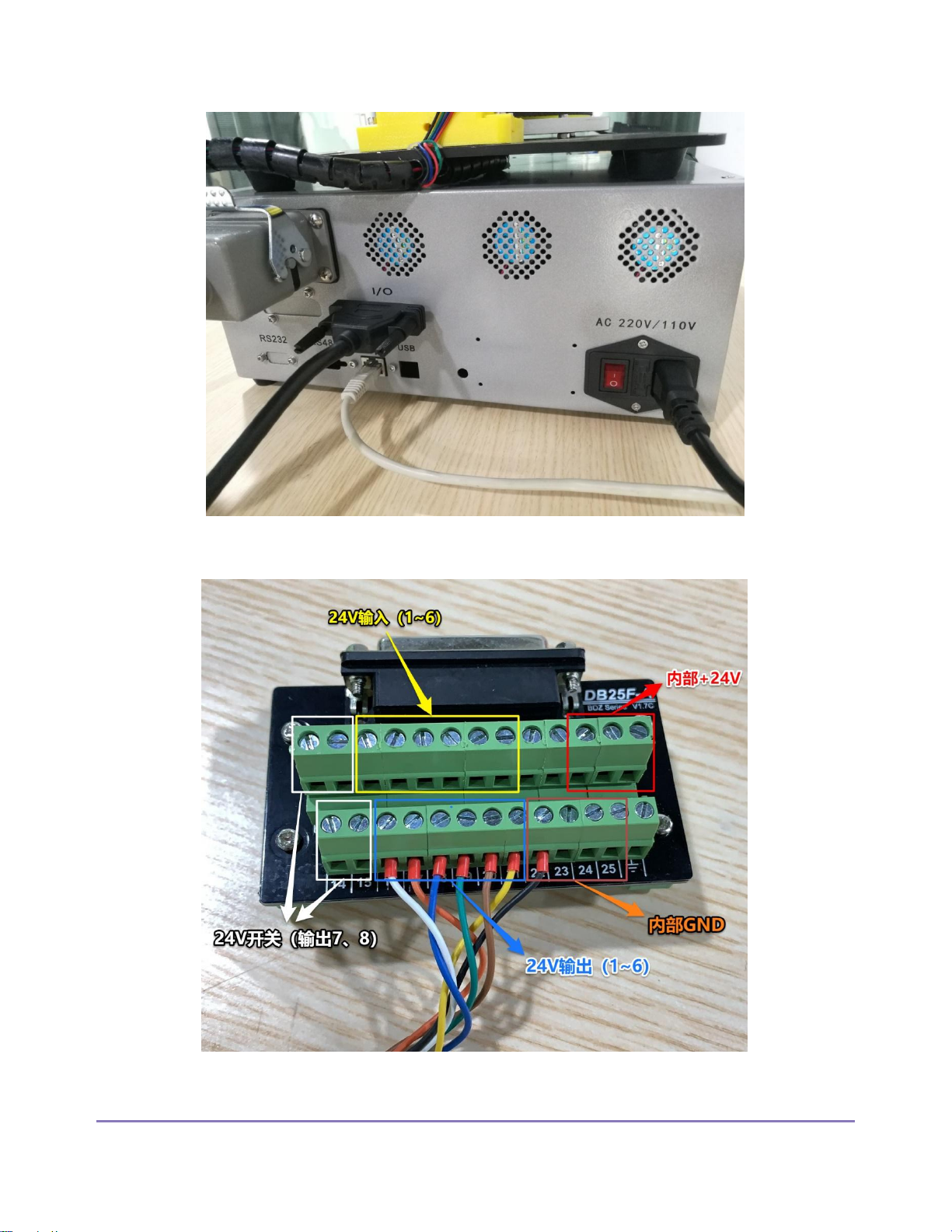
(4)Connect one end of the DB25 cable to the IO port of the control box of the robot arm, and
the other end to the DB25 relay station. The relay station leads to the relay module, which can
connect the external 24V output device, and the external 24V input device can be directly
connected to the input port of DB25 relay station .

2020-01-27
Manual for PROBOT Anno robot arm 8
Physical system connection diagram
2020-01-27
Manual for PROBOT Anno robot arm 9
connection of control box diagram
DB25 relay station connection

2020-01-27
Manual for PROBOT Anno robot arm 10
1.2 Adjust the initial pose of the robot arm
Before the control box can be started electrically, the arm must be returned to its original
position! The starting position of each axis of the robot arm should be reset to zero, otherwise the
manipulator is likely to run out of order, causing damage to the arm and causing danger.
Physical picture of the initial position of the robot arm
Inhaltsverzeichnis
Beliebte Robotik Handbücher anderer Marken

STEMCenter USA
STEMCenter USA Pi-Bot v2.00 Bedienungsanleitung

SunFounder
SunFounder PiDog Bedienungsanleitung

Universal Robots
Universal Robots UR5 Bedienungsanleitung

Universal Robots
Universal Robots E Series Bedienungsanleitung

YASKAWA
YASKAWA MOTOMAN-MPL80 II Bedienungsanleitung

EFORT
EFORT ECR5 Gebrauchsanweisung


