Protouch protouch Pro-10 system Handbuch

Vinten
Camera Control Solutions
Operators Guide
PRO-10
System

protouch
Pro-10
System
Publication Part No. 3809-8 Issue 2
Copyright © Vinten Broadcast Limited 2005
All rights reserved throughout the world. No part of this document may be stored in a retrieval system, transmitted, copied
or reproduced in any way including, but not limited to, photocopy, photograph, magnetic or other record without the prior
agreement and permission in writing of
Vinten Broadcast Limited.
Vinten is a registered trademark of Vinten Broadcast Limited.

3
Safety - read this first
Warning Symbols in this Operators Guide
Where there is a risk of personal injury, injury to others, or damage to the pan
and tilt head or associated equipment, comments appear, highlighted by the
word WARNING! and supported by the warning triangle symbol.
Technical data
Pro-10 pan and tilt head
Weight
Head with bowl clamp 2.5 kg (5.5lb)
Pan bar 0.25 kg (0.55 lb)
Height to mounting face 13.8 cm (5.4 in.)
Length 14.4 cm (5.7 in.)
Width 15.8 cm (6.2 in.)
Load capacity 10 kg (22 lb)
Tilt range +90° -60°
Pan range 360°
Tripod fixing 75 mm ball
Pozi-Loc tripod
Levelling bowl diameter 75 mm
Maximum height with floor spreader 156.2 cm (61.5 in.)
Minimum height with floor spreader 41.6 cm (16.4 in.)
Weight 3.2 kg (7.0 lb)
Transport length 71 cm (28.0 in.)
Recommended maximum load 25 kg (55 lb)
Floor spreader
Maximum leg radius 77 cm (22.5 in.)
Minimum leg radius 38 cm (15 in.)
Weight 0.7 kg (1.5 lb)

4
Further information
For full details on maintenance and spare parts, please refer to protouch Pro-10 System - Main-
tenance Manual and Illustrated Parts List (Publication Part No. 3809-9) This is obtainable from
Vinten Broadcast Limited or your local Vinten distributor. For information on-line, visit our website
at
www.vinten.com.

5
Contents
Page
Safety - read this first . . . . . . . . . . . . . . . . . . . . . . . . . . . . . . . . . . . . . . . . . . . . . . . . . . . . . . . . 3
Technical data . . . . . . . . . . . . . . . . . . . . . . . . . . . . . . . . . . . . . . . . . . . . . . . . . . . . . . . . . . . . . . 3
Further information. . . . . . . . . . . . . . . . . . . . . . . . . . . . . . . . . . . . . . . . . . . . . . . . . . . . . . . . . . 4
Introduction
Pro-10 pan and tilt head . . . . . . . . . . . . . . . . . . . . . . . . . . . . . . . . . . . . . . . . . . . . . . . . . . . 10
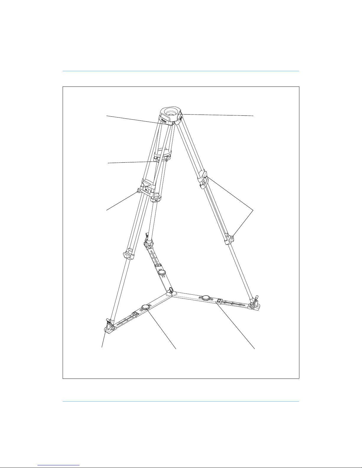
Pozi-Loc tripod . . . . . . . . . . . . . . . . . . . . . . . . . . . . . . . . . . . . . . . . . . . . . . . . . . . . . . . . . . . 11
Floor spreader . . . . . . . . . . . . . . . . . . . . . . . . . . . . . . . . . . . . . . . . . . . . . . . . . . . . . . . . . . . 11
Operation
Assembly
Tripod and spreader . . . . . . . . . . . . . . . . . . . . . . . . . . . . . . . . . . . . . . . . . . . . . . . . . . . . 13
Pan and tilt head. . . . . . . . . . . . . . . . . . . . . . . . . . . . . . . . . . . . . . . . . . . . . . . . . . . . . . . 13
Mounting the camera . . . . . . . . . . . . . . . . . . . . . . . . . . . . . . . . . . . . . . . . . . . . . . . . . . . . . . 13
Pan and tilt brakes . . . . . . . . . . . . . . . . . . . . . . . . . . . . . . . . . . . . . . . . . . . . . . . . . . . . . . . . 14
Pan and tilt drag. . . . . . . . . . . . . . . . . . . . . . . . . . . . . . . . . . . . . . . . . . . . . . . . . . . . . . . . . . 14
Optional equipment
Carrying strap . . . . . . . . . . . . . . . . . . . . . . . . . . . . . . . . . . . . . . . . . . . . . . . . . . . . . . . . . . . 15
'Spread-Loc' mid-level spreader . . . . . . . . . . . . . . . . . . . . . . . . . . . . . . . . . . . . . . . . . . . . . 16
Dollies . . . . . . . . . . . . . . . . . . . . . . . . . . . . . . . . . . . . . . . . . . . . . . . . . . . . . . . . . . . . . . . . . 17
Servicing
General . . . . . . . . . . . . . . . . . . . . . . . . . . . . . . . . . . . . . . . . . . . . . . . . . . . . . . . . . . . . . . . . 18
Cleaning. . . . . . . . . . . . . . . . . . . . . . . . . . . . . . . . . . . . . . . . . . . . . . . . . . . . . . . . . . . . . . . . 18
Routine maintenance. . . . . . . . . . . . . . . . . . . . . . . . . . . . . . . . . . . . . . . . . . . . . . . . . . . . . . 18
Battery replacement . . . . . . . . . . . . . . . . . . . . . . . . . . . . . . . . . . . . . . . . . . . . . . . . . . . . 19
Adjustments
Camera slide plate knob adjustment . . . . . . . . . . . . . . . . . . . . . . . . . . . . . . . . . . . . . . . 21
‘Pozi-Loc’ tripod leg clamp adjustment . . . . . . . . . . . . . . . . . . . . . . . . . . . . . . . . . . . . . . 22
Parts list. . . . . . . . . . . . . . . . . . . . . . . . . . . . . . . . . . . . . . . . . . . . . . . . . . . . . . . . . . . . . . . . . . 24
Associated publications
protouch Pro-10 System - Maintenance Manual
Publication Part No. 3809-9

6
Pro-10 Pan and Tilt Head
(1)
(2)
(3)
(4)
(6)
(5)
(7)
(8)
(9)
(10)
(11)
(12)
(13)
(14)
(16)
(17)
(18)
(15)

7
(1) 3/8 in. camera screw
(2) Slide lock release
(3) Pan bar
(4) Tilt brake
(5) Locating pin
(6) 3/8 in. camera screw stowage
(7) Camera slide plate clamp
(8) Tilt drag control
(9) Bowl clamp
(10) Illuminated levelling bubble
(11) Pan brake
(12) Pan bar mounting
(13) Levelling bubble illumination switch
(14) Camera slide plate
(15) Camera slide plate bung
(16) Battery compartment
(17) Pan drag control
(18) 1/4 in. camera screw

8
Pozi-Loc Tripod and Spreader
(19)
(20)
(21)
(22)
(24)
(23)
(25)
(26)

9
(19) Tripod bowl
(20) Clamp knob
(21) Floor spreader
(22) Floor spreader adjuster
(23) Foot securing strap
(24) Leg tie strap
(25) Attachment point for optional Spread-Loc mid-level spreader
(26) Tie down hook

10
Introduction
The protouch Pro-10 system from Vinten comprises a Pro-10 pan and tilt head, a Pozi-Loc two-
stage tripod, an adjustable floor spreader and a soft case.
Pro-10 pan and tilt head
The Pro-10 pan and tilt head is designed to support the latest professional digital video cameras,
up to 10 kg (22 lb) in weight. It embodies fluid drag assemblies for pan and tilt motions with brakes
on each axis to lock the head in any position. An illuminated levelling bubble is fitted to the rear of
the head and a quick-release, adjustable slide plate is provided for camera mounting. A single
fixed pan bar is supplied.
Balance graph
200
190
160
180
170
150
140
130
120
110
100
90
80
70
60
50 34567 kg
2
3
4
5
6
7
8
in. mm
6 8 10 12 14 lb
Payload
Centre of Gravity (C of G) Height
2
4
8910
16 18 20 2 2
Inhaltsverzeichnis


