Prozeda SOLAREG II VISION plus Bedienungsanleitung

Installation and Operating Instructions
SDC 204 1316BED035-10B-E Date 12/06
- 1 -
MICROPROCESSOR-CONTROLLED SYSTEM CONTROL UNIT FOR SOLAR
THERMAL SYSTEMS
SOLAREG II
VISION PLUS
IMPORTANT
!
Before installing and using this device, you must read through the instructions carefully.
Failure to observe the instructions and safety information contained in these installation and
operating instructions will void the guarantee for the device described/installed.
Store these instructions in a safe place.
Installation and Operating Instructions

Installation and Operating Instructions
SDC 204 1316BED035-10B-E Date 12/06
- 2 -
The described appliance has been made and tested in compliance with CE-guidelines.
1SAFETY INSTRUCTIONS 3
2SYMBOLS AND ABBREVIATIONS 4
3DEVICE DESCRIPTION 5
3.1 Usage 5
3.2 Device features 5
4SYSTEM DIAGRAMS 6
4.1.1 Over voltage protection 7
5DEVICE INSTALLATION 8
5.1 Opening the device (only by qualified personnel) 8
5.2 Wall mounting 9
6ELECTRICAL CONNECTION 10
6.1 230 V connections 11
6.1.1 Overview: 230 V connections for Solareg Vision Plus 11
6.2 Attachment of temperature sensor 11
7OPERATION / INDICATORS 13
7.1 Overview of displays and operating controls 13
7.2 Display – maximum display 14
7.3 Explanation of graphic symbols 14
7.4 Example of device operation 17
8MENU STRUCTURE 18
8.1 Overview 19
8.2 “Info” menu 20
8.3 “Program” menu 21
8.4 “Manual operation” menu 22
8.5 “Basic settings” menu 22
9CONTROLLER FUNCTIONS 24
9.1 General control functions 24
9.1.1 Load storage cylinder 24
9.1.2 Systems with two storages 25
9.1.3 Rotating speed controller 25
9.1.4 Independant controller 25
9.1.5 Thermostat (cooling) 26
9.1.6 Thermostat (heating) 26
9.1.7 Temperature difference control 27
9.1.8 Tube collector 27
9.2 System monitoring 28
9.2.1 Sensor monitoring 28
9.2.2 Flow monitoring 28
9.2.3 Collector protection / Re-cooling 29
9.2.4 System protection function 29
9.2.5 Frost protection 29
9.3 Additional functions 30
9.3.1 Yield estimation / yield metering 30
9.3.2 Engine-hour meter 30
10 RECTIFICATION OF FAULTS 31
10.1 Faults with error message 31
10.2 Faults without error message 32
11 TECHNICAL DATA 33
12 RESISTANCE TABLE PT1000 33
13 LIMITED WARRANTY 34

Installation and Operating Instructions
SDC 204 1316BED035-10B-E Date 12/06
- 3 -
1 S
AFETY INSTRUCTIONS
This control unit must be disconnected from the mains before any
installation and wiring work is carried out.
This device may only be opened, connected and commissioned by trained
personnel. In so doing, the relevant safety regulations of your country must
be adhered to.
•Prior to any installation or wiring
work on the electric motors, always
fully disconnect the device from the
operating voltage and ensure that the
mains supply cannot be reactivated.
Never mix up the connections for the
protective safety low voltage area
(sensor, flow meter) with the 230 V
connections. This could result in
damage and hazardous voltages to the
device itself and to the attached sensors
and devices.
•Solar thermal systems can become very
hot. There is a risk of being burnt. Take
care when installing the temperature
sensor.
•Install the Solareg Vision Plus in such a
way that no excessive operating
temperatures (>50°C) result, e.g. as a
result of heat sources.
•The device is not protected against
splashing and dripping. You should
therefore install it in a dry location.
•For safety reasons, the system may be
manually operated only for test
purposes. In this operating mode, there
is no monitoring of maximum
temperatures or sensor functions.
•If there are signs of damage to the
control unit, cables or attached pumps
and valves, the systems must not be
operated.
•Check whether the materials used for
the piping, thermal insulation, pumps
and valves are suitable for the
temperatures that will occur in the
system.
If you have any questions concerning your solar thermal system or your control unit, please
contact your installer or supplier for advice.

Installation and Operating Instructions
SDC 204 1316BED035-10B-E Date 12/06
- 4 -
2 S
YMBOLS AND ABBREVIATIONS
Explanation of symbols used in operating instructions:
Warning!
This symbol indicates potential dangers and errors
Warning: 230 Volts
This symbol indicates risk to life through high voltages.
•
List
i
Information on operation/special features
Instructions/procedure
?
Test/check
Keypad for control unit
Frequently used abbreviations
Abbreviat
ion Meaning Abbrevia
tion Meaning
TColl Temperature of collector [°C]
Min Minimum value
TCyl
Temperature of storage cylinder
[°C] Max. Maximum value
TTh Temperature for thermostat [°C] K Kelvin unit, corresponds to 1 degree
temperature difference
TCret Temperature of collector – return
line °C Degree Celsius unit
TFrost Temperature - frost protection Td Temperature differential controller
kWh Energy yield in kWh % Percent
xxx Miscellaneous display value
Term explanations
Unit A unit is a component of a system and is responsible for part of its
function.
Hysteresis In control technology, the term hysteresis is used where an upper and
lower threshold value is responsible for switching (see Td Start and Td
Stop).
Shield Electrical shields reduce the influence of electrical and magnetic fields on
the signals in the cables and wires. Coaxial cables are commonly used
for this purpose.
Heat station Place at which energy is stored or transferred. In solar thermal systems,
the storage cylinder is the heat station.

Installation and Operating Instructions
SDC 204 1316BED035-10B-E Date 12/06
- 5 -
3 D
EVICE DESCRIPTION
3.1 Usage
The solar thermal controllers Solareg Vision
Plus are high-performance, microprocessor-
controlled control devices used to control
the function of solar thermal systems.
The control units are suitable for common
types of solar thermal systems. See system
diagram.
These control units are designed for use in
dry rooms, private homes, business and
commercial premises.
Alternative use or use beyond this remit is
not in accordance with its purpose. Incorrect
usage can result in serious injury or death
to the user or a third party and can harm the
device or system and other material assets.
The manufacturer/supplier shall not be
liable for any damage arising from such
misuse. The risk is borne by the user alone.
3.2 Device features
The Solareg Vision Plus range offers the following features and equipment:
•Self-explanatory, menu-driven
operation
•Digitally adjustable control values
•System monitoring
•Energy yield estimation
•Storage of all entered values
•Large space for wiring
•Supports tube collectors
•Backlight display (on demand)
•Time counter-operating hours
•Diversity system protections
•Independent differential controller
with three time slots
•Third output alternatively for
thermostat, cooling function or the
independent differential controller
Available accessories:
•Temperature sensor PT1000
•Flow meter

Installation and Operating Instructions
SDC 204 1316BED035-10B-E Date 12/06
- 6 -
4 S
YSTEM DIAGRAMS
i
The following system diagrams are not to be understood as complete hydraulic circuit
diagrams.
TYPE 0:
1 collector, 1 storage
TYPE 1:
1 collector, 2 storages
pump-valve
TYPE 2:
1 collector, 2 storages
2 pumps
TYPE 3:
2 collector arrays, 1 storage
pump-valve
TYPE 4:
2 collector arrays, 1 storage
2 pumps
TColl Measuring point - collector
TCyl Measuring point - storage
cylinder
TCret Measuring point - collector
return line
TTh Measuring point - thermostat
P Pump
DFZ Flow meter

Installation and Operating Instructions
SDC 204 1316BED035-10B-E Date 12/06
- 7 -
Important notice concerning the valves in diagrams type 1 and type 3:
The system diagrams are propositions.
Regardless of the valve type shown above please follow this instructions:
Type1: one collector, two storages with valve:
•If not powered, the valve should connect the collector array with the storage 1.
•When powered, the valve must connect the collector array with the storage 2.
Type3: two collectors, one storage with valve:
•If not powered, the valve should connect the collector array 1 with the storage.
•When powered, the valve must connect the collector array 2 with the storage.
4.1.1 Over voltage protection
Prior to switching on or commissioning, you must ensure that the cover is
closed properly such that you feel and hear it click into position on both
sides.
SOLAREG II has integrated over voltage protection on every sensor input. Additional
safety measures are usually not required. For the collector sensor an additional
protection item is recommended and can be obtained from Prozeda GmbH. External
protection devices containing capacitors are not allowed as they will distort the
measurement.

Installation and Operating Instructions
SDC 204 1316BED035-10B-E Date 12/06
- 8 -
5 D
EVICE INSTALLATION
This contro
l unit may be installed only in dry rooms where there is no risk of
explosion. Installation on a flammable base is not permitted.
5.1 Opening the device (only by qualified personnel)
No tools are required to open the device.
The upper part of the casing is locked to the
lower part at two engagement points. The
locking forces are such as to prevent the
casing from being opened accidentally.
Holding the casing at each side, pull firmly towards you and then raise the top part of the
casing until it engages. You can now install and wire up the control unit.
Prior to switching on or commissioning, you must ensure that the cover is
closed properly such that you feel and hear it click into position on both
sides.

Installation and Operating Instructions
SDC 204 1316BED035-10B-E Date 12/06
- 9 -
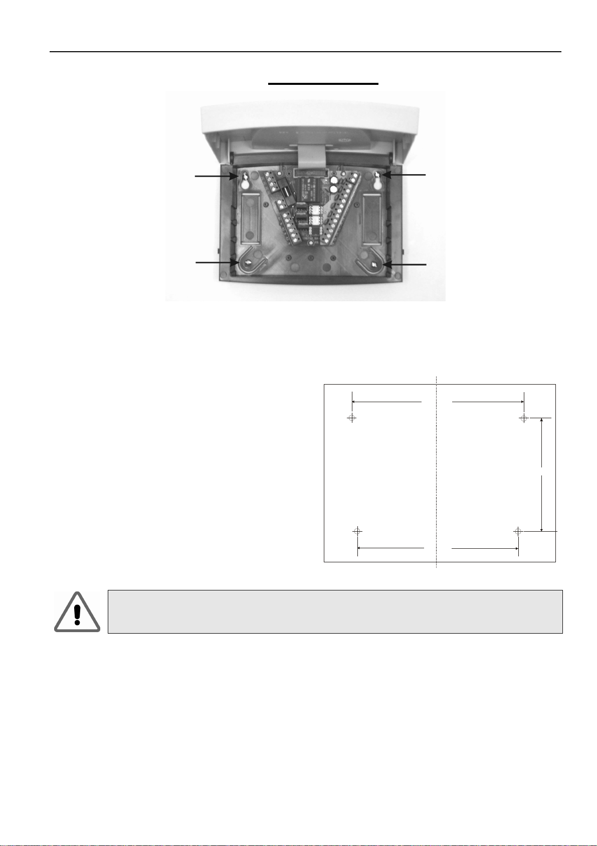
5.2 Wall mounting
When mounting the device on a wall,
proceed as follows:
•Drill the fixing holes using the drilling
template shown.
•Screw in the two top screws leaving
a gap of up to 6 mm.
•Open the device as described and
hang it on the two screws. You can
now fit the two bottom screws.
•To avoid damage to the lower part
of the casing, do not over tighten
any of the screws.
126mm
118mm
84mm
You drill into walls at your own risk. Prior to drilling, please check that there
are no cables, pipes or shafts in the wall; contact the property owner if
necessary.

Installation and Operating Instructions
SDC 204 1316BED035-10B-E Date 12/06
- 10 -
6 E
LECTRICAL CONNECTION
You must observe the safety instructions in chapter 1
The device may be opened only if it has been properly
disconnected from the mains and there is no risk of
reconnection.
All electrical cables are connected to the
unit in the lower part of the casing. The
terminals on the right-hand side are those
for the (low voltage) connections for sensor
and flow meter. The 230 V connections are
located on the left-hand side. The figure
below shows the terminal field for the
Solareg Vision Plus.
WMM
T1
T2
T3
T4
PE
L
N
N
A2
N
A1
Sicherung
Netzspannungs-
bereich
Kleinspannungs-
bereich
T5
T6
N
A3
PE Earth wire WM
M Flow meter
L Phase mains T1 Temperature sensor for collector 1
N Neutral cable for mains T2 Temperature sensor for storage 1
A1 Phase switching output 1 T3 Temperature sensor for collector 2 /
storage 2
A3 Phase switching output 2 T4 Temperature sensor for collector return
line
T5 Temperature sensor for heating /
cooling* or temperature differential
controller - source
T6 Temperature sensor for frost protection*
or temperature differential controller –
target or common measuring point
(autom. deactivated if not connected
* - free choice T1…T6
Andere Handbücher für SOLAREG II VISION plus
1
Inhaltsverzeichnis
Beliebte Steuereinheit Handbücher anderer Marken

Festo
Festo Compact Performance CP-FB6-E Stücklistenhandbuch

Elo TouchSystems
Elo TouchSystems DMS-SA19P-EXTME Bedienungsanleitung

JS Automation
JS Automation MPC3034A Bedienungsanleitung

JAUDT
JAUDT SW GII 6406 Series Kurzanleitung

Spektrum
Spektrum Air Module System Bedienungsanleitung

BOC Edwards
BOC Edwards Q Series Bedienungsanleitung