QTS P3 AN-X-TI-MAS Bedienungsanleitung

AN-X-TI-MAS
TI Remote I/O
Communication
Module
User Manual

Page
2
AN-X-TI-MAS November 2011
Because of the variety of uses for the products described in this
publication, those responsible for the application and use of these
products must satisfy themselves that all necessary steps have been taken
to assure that each application and use meets all performance and safety
requirements, including any applicable laws, regulations, codes and
standards. In no event will Quest Technical Solutions be responsible or
liable for indirect or consequential damage resulting from the use or
application of these products.
Any illustrations, charts, sample programs, and layout examples shown
in this publication are intended solely for purposes of example. Since
there are many variables and requirements associated with any particular
installation, Quest Technical Solutions does not assume responsibility or
liability (to include intellectual property liability) for actual use based
upon the examples shown in this publication.
Throughout this manual we use notes to make you aware of safety
considerations.
WARNING!
Identifies information about practices or circumstances that can lead to
personal injury or death, property damage, or economic loss.
These warnings help to:
•identify a hazard
•avoid the hazard
•recognize the consequences
IMPORTANT! Identifies information that is especially important for successful
application and understanding of the product.
TIP Identifies information that explains the best way to use the
AN-X-TI-MAS
Microsoft is a registered trademark of Microsoft Corporation.
Windows, Windows XP Windows Vista and Windows 7 are trademarks of Microsoft Corporation.
ControlLogix, RSLinx and RSLogix 5000 are trademarks of the Allen-Bradley Company, Inc.

AN-X-TI-MAS MODULE OVERVIEW 2
Hardware Features 3
Package Contents 3
Modes of Operation 4
INSTALLATION 5
Prevent Electrostatic Discharge 5
Power 5
Cabling and Termination 5
Ethernet Cabling 6
Software Installation 6
QUICK START 7
ETHERNET CONFIGURATION 8
Ethernet Configuration 8
Example: Standalone Computer 13
Reconfiguring an AN-X from an Unknown State 18
NETWORK CONFIGURATION 19
Autoconfiguration 19
Manual Configuration 21
Configuration File Format 21
Viewing the Current Configuration 22
Saving the Current Configuration 23
EXCHANGING SCHEDULED DATA WITH A CONTROLLOGIX 24
Mapping I/O Data 24
Other Mappable Data 28

Page
4
AN-X-TI-MAS November 2011
Viewing the Current Configuration 33
Saving the Current Configuration 33
Configuring the AN-X Module in RSLogix 5000 33
Input Only Connections 35
ControlLogix Alias Tags 38
Using the ControlLogix Log 40
USING ANXINIT 41
AnxInit Log 41
Locating Available AN-X Modules 42
Selecting an AN-X 43
Set AN-X IP Configuration 44
Restart an AN-X 45
AN-X Info 45
Read Kernel Parameters 46
Run Config Mode 46
Update AN-X Flash 47
Update Firmware 47
Firmware Update Wizard 48
Update Firmware Command 51
Patch Firmware 51
USING THE WEB INTERFACE 53
I/O Network 54
Configure ControlLogix Support 55
View Configuration Files 56
View Active Configuration 57
Log Files 58
System Error Log 58

System Info Log 58
ControlLogix Log 58
View All Logs 58
Administration Menu 58
Browse File System 58
AN-X IP Configuration 59
Archive Configuration 60
TROUBLESHOOTING 61
LEDs 61
Ethernet LEDs 61
SYS LED 61
NET LED – Network Status 62
UPDATING THE FIRMWARE 63
Reading Version Numbers 63
SUPPORTED MODULE TYPES 64
Low Density Modules 64
High-Density Non-mixed Modules 65
High-Density Mixed Modules 66
SPECIFICATIONS 67
SUPPORT 68
WARRANTY 69

AN-X-TI-MAS Module Overview
The AN-X-TI-MAS communications module connects a ControlLogix
PLC or other device to a TI 505 remote I/O network.
The module acts as a scanner on the remote I/O network, reading inputs
and writing outputs. It supports up to 15 remote bases.
A ControlLogix processor communicates with the module using
scheduled connections over Ethernet, to read inputs from the TI remote
I/O network and write outputs.
The AN-X-TI-MAS module has a web interface for configuration. You
can communicate with the module using any standard web browser such
as Internet Explorer.
The module firmware can be updated over Ethernet using the Windows
utility supplied. Refer to page 63 for details.
Please note: To connect this module to an existing coaxial network you
will need a RS-485/RF I/O Channel Converter, (PPX:505-6860).
It is available from Siemens Industrial Automation Inc. distributors. For
assistance in locating your distributor call 1-800-964-4114.
Reference documents are available for download from
www.prosoft-technology.com .
AN-X-TI-MAS Page
3
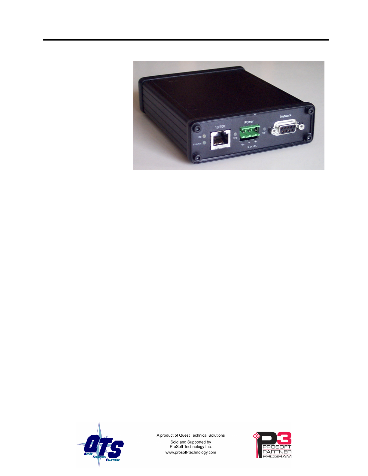
Hardware Features
The module has:
•LEDs to indicate the status of the connection to the Ethernet (100
and Link/Act)
•a LED to indicate the module’s internal state and the state of
communication with the ControlLogix (SYS)
•a LED to indicate the state of communications on the TI remote I/O
network (NET)
•an Ethernet connector
•a power connector
•a 9-pin connector to connect to the TI remote I/O network
A watchdog timer is implemented in the module’s hardware. If the
firmware does not kick the watchdog within the timeout period the
watchdog times out and places the module into a safe fatal failure state.
A jabber inhibit timer is implemented in the module’s hardware. If the
network transmitter is on longer than 150% of the longest network
frame time, the transmitter is forced off and the module is placed into a
safe fatal failure state.
Package Contents
•AN-X-TI-MAS module
•CD containing software and documentation
•rubber feet for desktop use

Page
4
AN-X-TI-MAS November 2011
Modes of Operation
There are three AN-X modes of operation:
•Boot mode. The AN-X is running its low level startup firmware.
•Configuration mode. This is the mode when you are updating the
firmware in the AN-X.
•Production mode. This is the normal runtime mode of operation.

AN-X-TI-MAS Page
5
Installation
Prevent Electrostatic Discharge
The module is sensitive to electrostatic discharge.
WARNING! Electrostatic discharge can damage integrated circuits or
semiconductors. Follow these guidelines when you handle the module:
•Touch a grounded object to discharge static potential
•Do not touch the connector pins
Power
AN-X requires a DC power input of anywhere from 12 to 24 VDC.
Left to right the pins on the power connector are chassis ground, negative
voltage and positive voltage.
The chassis ground should be connected.
Power consumption is 300 mA @ 12VDC or 150 mA @ 24VDC.
The part number for the power connector is Phoenix MSTB
2.5/3-ST-5.08
Contact QTS if you need a suitable wall adapter.
Cabling and Termination
Refer to the Simatic TI545/TI555 System Manual, publication
PPX:545/555–8101-2 for detailed information on cabling and
installation.
The module has a standard 9-pin connector for connection to the remote
I/O network. The AN-TI-MAS is wired just like a TI scanner. Follow
the TI recommendations for termination.

Page
6
AN-X-TI-MAS November 2011
Ethernet Cabling
AN-X has a standard RJ-45 connector for connecting to Ethernet.
If you are connecting to the AN-X through a router or switch, use a
standard Ethernet cable.
If you are connecting directly to the AN-X module, use a crossover
cable.
Software Installation
You must uninstall any previous version of the software before you can
install a new version. Use the Windows Control Panel Add and Remove
Programs to remove the old version.
Insert the CD supplied with the AN-X module and run the program
setup.exe on the CD.
Inhaltsverzeichnis
Andere QTS Steuereinheit Handbücher


Beliebte Steuereinheit Handbücher anderer Marken

Festo
Festo Compact Performance CP-FB6-E Stücklistenhandbuch

Elo TouchSystems
Elo TouchSystems DMS-SA19P-EXTME Bedienungsanleitung

JS Automation
JS Automation MPC3034A Bedienungsanleitung

JAUDT
JAUDT SW GII 6406 Series Kurzanleitung

Spektrum
Spektrum Air Module System Bedienungsanleitung

BOC Edwards
BOC Edwards Q Series Bedienungsanleitung


