Rain i-dial Bedienungsanleitung

N N O V A T I V E I R R I G A T I O N S Y S T E M S
I
EN. INSTRUCTIONS
Vac

ENGLISH
RAIN s.p.a.
via Kennedy 38/40
20023 Cerro Maggiore
ITALY (MI)
16
INDICE
Pag. 17
TECHNICAL FEATURES
Pag. 18
THE CONTROLLER
Pag. 20
ELECTRICAL CONNECTIONS
Pag. 23
INSTALLING THE BATTERIES
CURRENT TIME AND DAY SETTING
Pag. 24
IRRIGATION PLANNING
Pag. 25
MANUAL START
Pag. 26
FUNZIONI AGGIUNTIVE - BUDGET
Pag. 27
ADDITIONAL FEATURES - EXTRA
PUMP
SENSOR
Pag. 28
PROBLEM SOLVING
DESCRIPTION
The new controller I-DIAL, available in
indoor and outdoor version 4-6-8 stations,
is ideal for all residential applications and
follows the philosophy to simplicity of
programming in 3 RAIN steps: start time,
duration and frequency.

ENGLISH
17
Technical features INDOOR version
• 4 - 6 - 8 stations
• indoor Model with external transformer
• Operating 220 VAC 50Hz
• Outputs 24 Volts AC, 0.8 AMP
• 4 independent programs
• 4 start times per program (one for each
program)
• Display of next irrigation
• Irrigation time from 1 min. 240 min. per station
• Watering cycles from 4 per day to 1 per week
• Irrigation program per weekly days or per
intervals from 1 to 19 days
• Seasonal adjustment from 10% to 200%
• Pump control and master valve (24 VAC out)
programmable per station
• Buffer batteries 2 x 1.5 volt AA alkaline (not
included)
• Output rain sensor programmable per station
• Function OFF
• Function Low-battery
• No permanent memory
Technical features OUTDOOR version
• 4 - 6 - 8 stations
• Model outdoor with internal transformer
• Operating 220 VAC 50Hz
• Outputs 24 Volts AC, 1.0 AMP
• 4 independent programs
• 4 start times per program (one for each
program)
• Display of the next irrigation
• Irrigation time from 1 min. 240 min per station
• Watering Cycles 4 per day to 1 week
• Irrigation program per weekly days or per
intervals from 1 days to 19 days
• Seasonal adjustment from 10% to 200%
• Pump control and master valve (24 VAC out)
programmable per station
• Buffer batteries 2 x 1.5 volt AA alkaline (not
included)
• Output rain sensor programmable per station
• Function OFF
• Function Low-battery
• No permanent memory

ENGLISH
18
A
B
C
16
17
18
D
E
24 vacsensor c c m 12345678
SPA
TIME
START
RAIN DELAY
DURATION
WE
EVERY
TU
ALL
MO
DAY
%
SA
ZONE
FRTH SU
BA
HOURS
C D
LOW
PROG
NEXT START
FERTILIZER
1 2 3
4
5 6 7 8
9
10
11
12
13
1415
indoor
model
outdoor
model
WARNING
The version with the outside transformer
must be installed in shelter of weather
THE CONTROLLER

ENGLISH
19
Dial
A
When the dial is in this position the control-
ler do the irrigation as programming
When the dial is in this position you
can set time and date.
When the dial is on one of these
symbols you can set a start time irrigation
When the dial is on one of these symbols
you can set the watering duration of the
indicated sector
When the dial is on one of these symbols
you can set days or the frequency
irrigation
Programming button
B
Increases the selected item fl ashing in the
display
Confi rms values and let continue the pro-
gramming (ENTER)
Decreases the selected item fl ashing in the
display
Wiring Compartment
C
24 vac Cables transformer Input
sensor Rain sensor input
Pump control or master valve Output
M
Sector output
1...8
The button CLEAR eliminates programming
16
Protection fuse 1.0 A
17
button RESET restarts the controller
18
Extra bottons
D
It allows manual start irrigation
It allows you to personalize the start of
pump and sensor
It allows to adjusts irrigation times with a
percentage
Schermo retro illuminato
E
1 Il sensore pioggia è attivo
2 Le batterie tampone sono scariche
3 E’ attiva la funzione ritardo dell’irrigazione
4 Funzione non disponibile
5 Indica la prossima partenza
6 Indica l’ora di partenza
7 Indica i programmi
8 Indica un’irrigazione in corso
9 Indica la regolazione stagionale attiva
(budget)
10 Ore
11 Giorno
12 Indica il tempo d’irrigazione
13 Giorni della settimana
14 Indica l’intervallo d’irrigazione
15 Indica l’irrigazione manuale in corso

ENGLISH
20
OFF
SPA
OFF
OFF
OFF
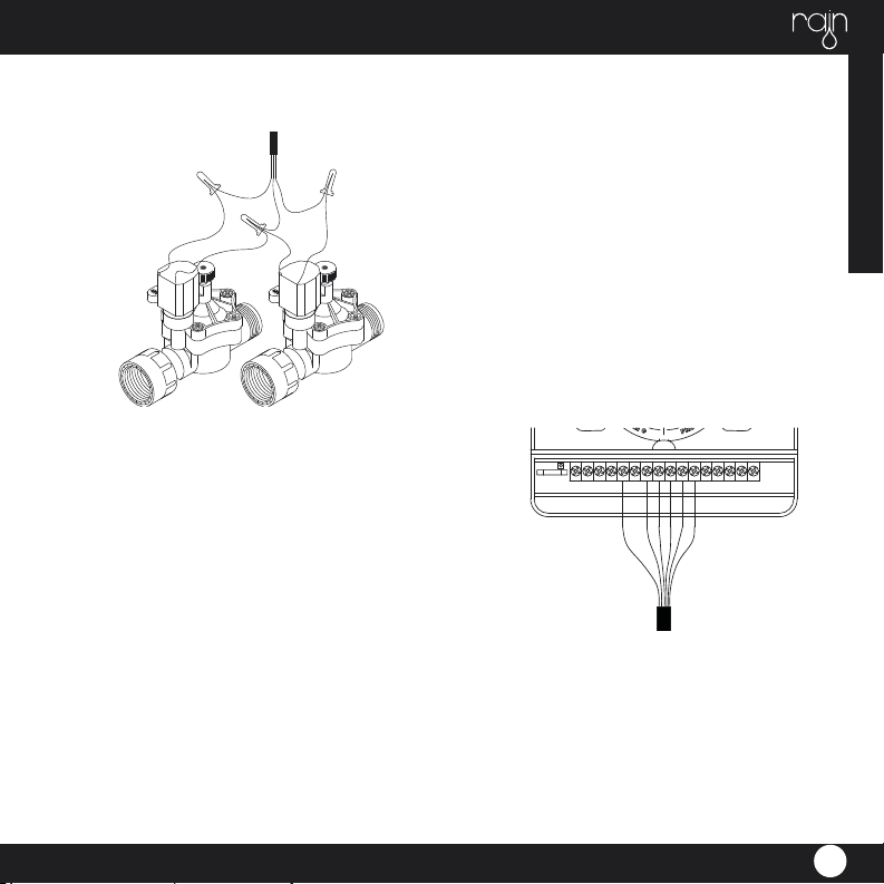
Elettrovalvola
zona 1
Elettrovalvola
zona 2
Elettrovalvola
zona 3
Elettrovalvola
zona 4
Filo comune
Cavo 24 vac
Cavo sensore
Each 24 VAC electric valve is equipped with two black cables. The fi rst one identifi es the number of
the area and it will be connected to one of the outputs numbered in the terminal compartment and
the second one is the common cable that will be connected to the Exit C in the terminal compart-
ment along with all common cables of all electric valves.
The cables of the 24 Vac electric valves have no polarity. Connect the sensor wires to two cables in
output SENSOR. For version INDOOR connect transformer’s cables to the 24-vac input.
ELECTRICAL CONNECTIONS
ENGLISH
21
OFF
OFF
• If the distance between the timer and valves is
less than 700 feet (210 M), use
WaterMaster® sprinkler wire or 20-gauge
(AWG) plastic jacketed thermostat
wire to connect the timer to the valves. If the
distance is over 700 feet (210 M),
• use 16-gauge (AWG) wire. Terminals accept
up to 14-gauge wire. The wire
can be buried in the ground; however, for more
protection wires can be pulled
through PVC pipe and buried underground. Be
careful to avoid burying the wires
in locations where they could be damaged by
digging or trenching in
the future.
• Each valve has two wires. One wire is to be
connected as the common. The
common wires for all the valves can be connec-
WIRING THE ELECTRIC VALVES
ted together to one common wire
CONNECTING VALVE WIRES TO THE
TIMER
• Remove the terminal compartment cover.
• Strip _” (6mm) of the plastic insulation off the
end of each wire.
• Determine which valve you want to connect to
which station. Connect each
valve wire to its station terminal (labeled 1-6) by
inserting the bare wire fully into
the terminal.
going to the timer. The other valve wire is to be
connected to the specifi c station wire that will
control that valve
• All wires should be joined together using wire
nuts, solder, or vinyl tape. For additional protec-
tion to waterproof connections a WaterMaster®
grease cap can be used
• To avoid electrical hazards, only one valve
should be connected to each station (Note:
Only one wire can be installed into each termi-
nal. If more than two common wires are used
in your system, splice several together so only
one wire runs into each of the COM terminals.
Protect the splice connection with a wire nut.)

ENGLISH
22
• It will be necessary to open the terminal to
allow for wire insertion or removal.
To do this you will need to use a small phillips
head screwdriver.
• Connect the common wire to the terminal
labeled “com”
CONNECTING THE TRANSFORMER
• With the wiring terminal shroud off, fi nd the
two terminal holes labeled “24vac”.
Make sure the transformer is not plugged in.
Insert one of the two power leads
from the transformer into each terminal.
• It will be necessary to open the terminal to
allow for wire insertion or removal.
To do this you will need to use a small phillips
head screwdriver.
• Plug in transformer
WARNING: DO NOT LINK TWO OR MORE
TIMERS TOGETHER WITH ONE
TRANSFORMER.
• Slide the shroud back on.
RAIN SENSOR
• A rain sensor or other type of micro-switch
weather sensor may be connected to
the controller. The purpose of the sensor is to
stop watering when precipitation is
suffi cient.

ENGLISH
23
SPA
TIME
MO
CURRENT TIME AND DAY SETTING
Turn the circular cursor on SET, the time will begin to
fl ash.
Modify the time with the + and - buttons, then press
ENTER to confi rm and move to the modifi cation of
minutes with + and -, press ENTER to confi rm and move
to the modifi cation of the day of the week with
+ and - buttons, press ENTER to confi rm.
After adjusting the time you can turn the cursor to the
right to continue with the watering cycles programming
or to the left to return to the auto function.
INSTALLING THE BATTERIES
Remove the battery compart-
vano batterie
ment by unscrewing the two
screws on the edges. Put two
AA (1.5 V) alkaline batteries in
the compartment.
Replace the battery compart-
ment in its place
and screw.
vano batterie
AA 1.5 V
AA 1.5 V
batterie
non fornite
Andere Handbücher für i-dial
1
Inhaltsverzeichnis
Andere Rain Controller Handbücher

Rain
Rain elite Vac Bedienungsanleitung

Rain
Rain TBD Bedienungsanleitung

Rain
Rain ZENIT VISION Bedienungsanleitung

Rain
Rain C-DIAL 24VAC Bedienungsanleitung

Rain
Rain s-dial smart Bedienungsanleitung

Rain
Rain AMICO PRO Bedienungsanleitung

Rain
Rain Evo 1 Bedienungsanleitung

Rain
Rain AMICO PRO Bedienungsanleitung


