resideo Q314 Bedienungsanleitung

INSTALLATION INSTRUCTIONS
69-0519-06
Q314 and Q327A Pilot Burners
APPLICATION
Pilot burners provide main burner ignition for standing pilot natural and LP gas systems. Used with a thermocouple to
provide automatic pilot safety control. Used with a thermopile in a self-powered system. See Table 1 for model
specifications.
Table 1. Model Specifications.
INSTALLATION
WHEN INSTALLING THIS
PRODUCT…
1. Read these instructions carefully. Failure to follow
instructions can damage product or cause a haz-
ardous condition.
2. Check ratings given in instructions and on product
to make sure product is suitable for your applica-
tion.
3. Make sure installer is a trained, experienced ser-
vice technician.
4. After completing installation, use these instruc-
tions to check out product operation.
WARNING
Fire or explosion hazard can cause property
damage, severe injury, or death.
Follow these warnings exactly.
1. Disconnect power supply before wiring to
prevent electrical shock or equipment
damage.
2. To avoid dangerous accumulation of fuel gas,
turn off gas supply at appliance service valve
before starting installation and perform Gas
Leak Test after completion of installation.
3. Do not bend pilot tubing at the control or pilot
after compression nut has been tightened.
Gas leakage at the connection may result.
Follow appliance manufacturer’s instructions if
available; otherwise, use instructions provided below.
Location
1. Position pilot burner for easy access, observation,
and lighting. In replacement applications, replace
pilot burner with an identical unit and position new
pilot burner in the same location and orientation
as the original pilot burner.
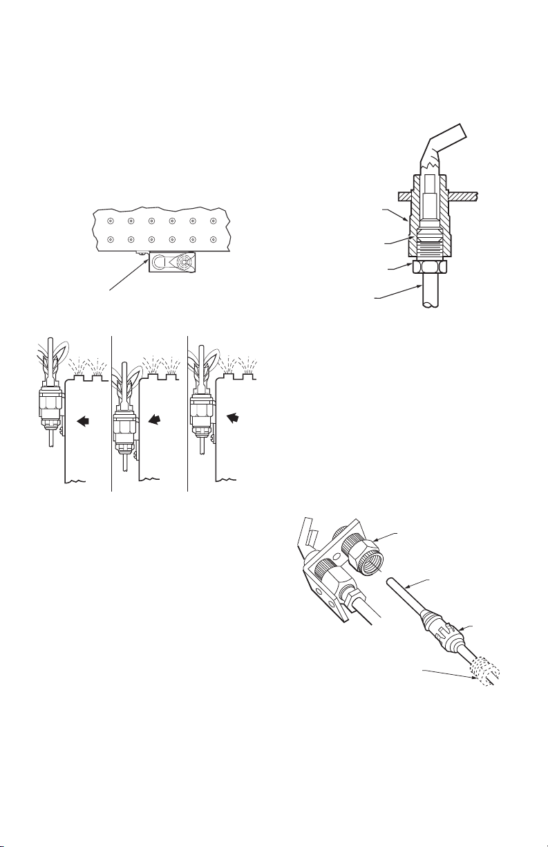
2. Mount pilot burner on main burner. Mounting sur-
faces other than the main burner can shift, bend,
or warp as furnace expands and contracts while
operating. See Fig. 1.
Model Primary Aerated Type of Orifice Pilot Tip Type Includes
Q314A No Insert Target Includes natural and LP gas
orifices, 1/4 in. compression
fitting, “F,” “K,” or “L” tip styles, “B”
mounting bracket, and “A”
mounting bracket adapter.
Q327A Yes Spud Target Includes natural and LP gas
orifices, 1/4 in. compression
fitting, and “B” mounting bracket
with screws.

Q314 AND Q327A PILOT BURNERS
69-0519—06 2
3. Mount pilot burner so the ignition flame remains
properly positioned with respect to the main burner
flame. See Fig. 2.
4. Supply pilot flame with ample air free of combus-
tion products.
5. Do not impinge pilot flame on adjacent parts. Do
not impinge main burner flame on pilot burner.
6. Do not expose pilot flame to falling scale which
could impair ignition of main burner.
7. Do not expose pilot burner to main burner rollout
while igniting or extinguishing.
8. Do not expose pilot flame to drafts that push or pull
pilot flame away from the thermocouple or thermo-
pile.
Fig. 1. Mount pilot burner on main burner.
Fig. 2. Location of pilot burner.
Connect Pilot Gas Tubing
1. Cut tubing to desired length and bend as necessary
for routing to pilot burner. Do not make sharp
bends or deform tubing. Do not bend tubing at con-
trol after compression nut has been tightened, as
this can result in gas leakage at connection.
2. Square off and remove burrs from end of tubing.
3. Push tubing into compression nut clearance hole
until tubing bottoms.
NOTE: When replacing a pilot burner or orifice, cut off
old compression fitting and replace with new
compression fitting provided with new pilot
burner. Never use old compression fitting as it
may not provide a gas-tight seal. See Fig. 3.
4. While holding tubing all the way in, engage threads
and turn until finger tight.
5. Using a wrench, turn compression nut one turn
beyond finger tight. DO NOT OVERTIGHTEN.
6. Connect other end of tubing to gas control accord-
ing to gas control manufacturer instructions.
Fig. 3. Always use new compression fitting.
Install Thermocouple or Thermopile
Push-In Design
1. Insert thermocouple or thermopile tip into hole or
barrel provided beneath pilot burner. See Fig. 4.
2. Push in firmly until thermocouple or thermopile is
locked into place.
Attachment Nut Design
1. Insert thermocouple or thermopile tip into hole or
barrel provided beneath pilot burner. See Figs. 4
and 5.
2. Engage attachment nut threads and tighten until
thermocouple or thermopile is locked into place.
Fig. 4. Installing thermocouple or thermopile.
PILOT
BURNER/GENERATOR
MUST BE RIGIDLY
POSITIONED
RELATIVE TO
MAIN BURNER
M1263A
PILOT BURNER/
IGNITION-
SENSOR
JUST RIGHT
PILOT BURNER/
IGNITION-
SENSOR
TOO LOW
PILOT BURNER/
IGNITION-
SENSOR
TOO HIGH
MAIN BURNER
FLAME WILL
IMPINGE ON
IGNITION-
SENSOR
IGNITION
FLAME WILL
IMPINGE ON
MAIN BURNER
IGNITION
FLAME JUST
MISSES
MAIN BURNER
M3285A
PILOT BURNER BODY
FITTING BREAKS OFF
AND CLINCHES TUBING
AS NUT IS TIGHTENED
TO GAS CONTROL
M3295B
TIGHTEN NUT ONE TURN
BEYOND FINGER TIGHT
PILOT BURNER
ASSEMBLY
THERMOCOUPLE
OR THERMOPILE
PUSH-IN
CLIP
M3286A
OPTIONAL
ATTACHMENT
NUT

Q314 AND Q327A PILOT BURNERS
369-0519—06
Fig. 5. Installing Q390 Thermocouple.
Install Bleed Gas Tubing (if used):
1. Route bleed gas tubing from bleed tapping on gas
control to the pilot burner.
2. Push clip into place. See Fig. 6.
3. Insert bleed gas tubing until 3/8 inch [10 mm] of
tubing is above pilot burner bracket. Tip of bleed
gas tubing must not extend into pilot flame.
Install “A” Mounting Bracket Adapter
(optional)
To convert mounting bracket from “B” mounting bracket
to “A” mounting bracket, install the “A” mounting bracket
adapter to the pilot burner mounting bracket. Then install
pilot burner to main burner.
Fig. 6. Bleed gas tube installation.
Change Insert Orifices (See Fig. 7)
1. Disconnect pilot tubing from the pilot burner and
remove insert orifice. Sometimes a light force is
required to remove the orifice.
2. Cut off old compression fitting.
NOTE: When replacing an orifice, cut off old compres-
sion fitting and replace with a new compression
fitting. Never use old compression fitting as it
may not provide a gastight seal. See Fig. 3.
3. Square off end of pilot tubing and remove all burrs.
4. Insert new compression nut over pilot tubing and
slide out of the way.
5. Insert new orifice into pilot burner and push pilot
tubing into the pilot burner until it bottoms.
6. While holding tubing all the way in, slide compres-
sion fitting into place and engage threads. Turn
until finger tight.
7. Using a wrench, tighten compression fitting one
turn beyond finger tight.
Change Spud Orifices (See Fig. 7)
1. Disconnect pilot tubing from orifice.
2. Unscrew old spud orifice and discard.
3. Cut off old compression fitting.
NOTE: When replacing an orifice, cut off old compres-
sion fitting and replace with a new compression
fitting. Never use old compression fitting as it
may not provide a gastight seal. See Fig. 3.
4. Square off end of pilot tubing and remove all burrs.
5. Insert new compression nut over pilot tubing and
slide out of the way.
6. Insert new orifice into pilot burner and tighten
securely.
7. Push pilot tubing into orifice until it bottoms.
8. While holding tubing all the way in, slide compres-
sion fitting into place and engage threads. Turn
until finger tight.
9. Using a wrench, tighten compression fitting one
turn beyond finger tight.
Fig. 7. Changing spud and insert orifices.
SCREW-IN TYPE
THERMOCOUPLE
ATTACHMENT NUT
M3269A
ADAPTER
PILOT BURNER
ASSEMBLY
THIS DIMENSION SHOULD BE
MAXIMUM OF 3/8 INCH (10 MM)
WHEN BLEED TUBE IS IN FINAL
POSITION
BLEED TUBE CLIP
1/8 IN. STEEL TUBING
M3284A
INSERT
ORIFICE
M27083A
SPUD
ORIFICE
INSERT
ORIFICE
CROSS SECTION

Q314 AND Q327A PILOT BURNERS
69-0519—06 4
STARTUP AND CHECKOUT
Perform a Gas Leak Test
WARNING
Fire or explosion hazard can cause property
damage, severe injury, or death.
Check for gas leaks with soap and water solution
any time work is done on a gas system.
Gas Leak Test
1. Ensure that gas supply is turned on at the appli-
ance service valve.
2. Paint pipe connections upstream of pilot burner
with rich soap and water solution. Bubbles indicate
gas leak.
3. If leak is detected, tighten pipe connections.
4. Stand clear of main burner while lighting to prevent
injury caused from hidden leaks which could cause
flashback in the appliance vestibule. Light main
burner.
5. With main burner in operation, paint pipe joints
(including adapters) and gas control inlet and out-
let with rich soap and water solution.
6. If another leak is detected, tighten adapter screws,
joints, and pipe connections.
7. Replace part if leak can not be stopped.
Adjust Pilot Flame
The pilot flame should envelop 3/8 to 1/2 in. [10 to 13
mm] of the thermocouple or thermopile tip. See Fig. 8. To
adjust pilot flame:
1. Remove pilot adjustment cover screw from gas
control.
2. Turn inner pilot adjustment screw clockwise to
decrease or counterclockwise to increase pilot
flame.
3. Always replace pilot adjustment cover screw and
tighten firmly after completing adjustment to
ensure proper operation.
Fig. 8. Thermocouple or thermopile tip must be in pilot
flame.
Ignite Pilot Burner
1. Before lighting pilot burner, turn thermostat to its
lowest setting. Wait for unburned gas to vent.
NOTE: LP gas is heavier than air and will not vent
upward. Smell for LP gas next to floor. If you
smell gas, shut off the main valve in the gas pip-
ing, or, ON LP, AT THE TANK. Perform Gas Leak
Test to recheck all connections.
2. Light pilot burner according to appliance manufac-
turer’s instructions.
SERVICE
WARNING
Fire or explosion hazard can cause property
damage, severe injury, or death.
Perform Gas Leak Test anytime work is done to
the system.
Pilot Outage
1. If pilot flame goes out during normal operation, but
is properly adjusted, recheck Mounting and Loca-
tion instructions on page 1.
2. If all mounting and location instructions are fol-
lowed but pilot continues to go out, construct
shielding to protect pilot flame from main burner
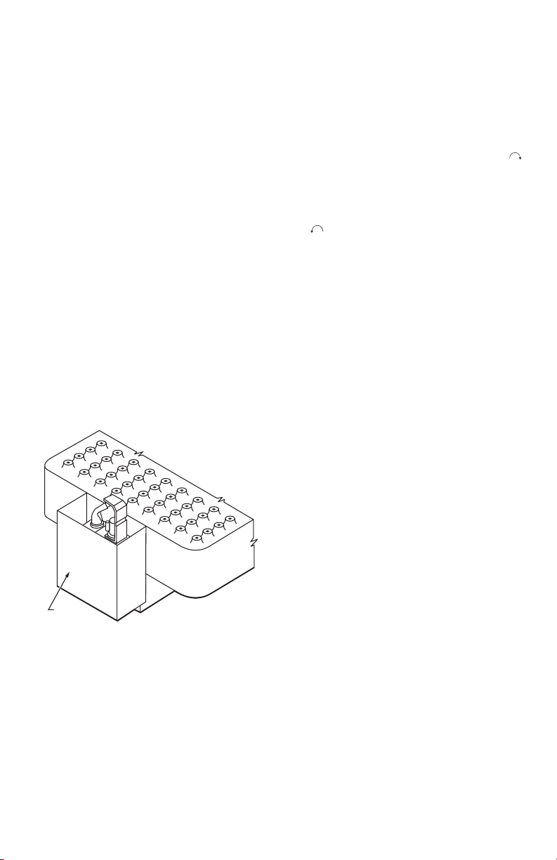
ignition and extinction and drafts. See Fig. 9.
3. Check pilot flame characteristics.
• Check the pilot flame with the main burner
operating.
• Ensure the pilot flame continuously covers the
top 3/8 to 1/2 in. [10 to 13 mm] of the
thermocouple or thermopile. See Fig. 8.
• Ensure the pilot flame is blue (a yellow tipped
flame is acceptable on LP systems), soft and
steady. See Fig. 9 for examples of possible pilot
flame problems and their causes.
• If pilot burner is damaged, replace it with an
identical pilot burner and mount and position in
the same location and orientation.
Fig. 9. Examples of unsatisfactory pilot flames.
THERMOCOUPLE
OR THERMOPILE
PROPER
FLAME
ADJUSTMENT 3/8 TO 1/2 INCH
(10 TO 13 MILLIMETERS)
M1973D
LAZY YELLOW FLAME
WAVING BLUE FLAME
NOISY LIFTING
BLOWING FLAME
HARD SHARP FLAME
SMALL BLUE FLAME CHECK FOR LACK OF GAS FROM:
• CLOGGED ORIFICE FILTER
• CLOGGED PILOT FILTER
• LOW GAS SUPPLY PRESSURE
• PILOT ADJUSTMENT AT MINIMUM
CHECK FOR LACK OF AIR FROM:
• DIRTY ORIFICE
• DIRTY LINT SCREEN, IF USED
• DIRTY PRIMARY AIR OPENING,
IF THERE IS ONE
• PILOT ADJUSTMENT AT MINIMUM
CHECK FOR:
• EXCESSIVE DRAFT AT PILOT
LOCATION
• RECIRCULATING PRODUCTS
OF COMBUSTION
CHECK FOR:
• HIGH GAS PRESSURE
THIS FLAME IS CHARACTERISTIC
OF MANUFACTURED GAS
CHECK FOR:
• HIGH GAS PRESSURE
• ORIFICE TOO SMALL
M3272B
APPEARANCE CAUSE

Q314 AND Q327A PILOT BURNERS
569-0519—06
Pilot Safety Control Power Unit Failure
1. Ensure pilot flame is properly adjusted.
2. Ensure power unit connections clean and tight.
3. If power unit still fails to hold in, use the W129A
Millivoltmeter to obtain the open and closed circuit
voltage generated by the thermocouple or genera-
tor.
4. Compare measured open and closed circuit voltage
values to Acceptable Range Charts in W129A Man-
ual.
5. If W129A Millivoltmeter or other meter is not avail-
able, replace thermocouple or thermopile. If this
does not correct the condition, replace power unit.
Thermocouple or Thermopile
Performance
Thermocouples and thermopiles require proper
temperature differential between the hot-junction (tip)
and coldjunction (base) to provide satisfactory operation
of gas controls. Thermocouples and thermopiles perform
less effectively when exposed to excessive cold-junction
or hotjunction temperatures.
Excessive cold-junction temperatures can be caused by
heat radiation from adjacent surfaces or high ambient air
temperatures. Excessive cold-junction temperatures can
be eliminated by shielding the pilot flame, see Fig. 10, or
constructing a baffle to direct secondary air over the pilot
burner base.
Excessive hot-junction temperatures can be eliminated
by proper pilot flame adjustment. To adjust pilot flame,
see Adjust Pilot Flame section.
Fig. 10. Proper shielding of pilot flame.
Pilot Turndown Test (30 mV safety control
systems)
The Pilot Turndown Test assures that the pilot flame
ignites the main burner within four seconds from the
time gas reaches the main burner. In this test, the pilot
flame is just sufficient enough to hold in the power unit
or just above the point of flame extinction (whichever
occurs at a higher pilot gas flow rate).
1. With the pilot and main burner operating, shut off
the main burner by either lowering the thermostat
temperature setting or turning the gas control knob
to the PILOT position.
NOTE: If using a W129A Millivoltmeter, turn the pilot
gas adjustment screw until the thermocouple
open circuit voltage is 2 mV. Omit steps 2,3, and
4 and proceed with step 5.
2. Turn the pilot gas adjustment screw clockwise
until the pilot begins to decrease in size. Then, turn
the pilot gas adjustment screw clockwise 1/4 turn
a time (waiting one minute between each turn to
allow the thermocouple to cool) until safety shutoff
power unit just drops, causing safety shutdown.
3. Turn pilot gas adjustment screw counterclockwise
slightly.
4. Relight pilot burner. The power unit should hold in.
5. Turn gas control knob to ON position and set ther-
mostat temperature setting above room tempera-
ture. Main burner should light within four seconds
without flame rollout. If not, check pilot mounting
and location instructions in Location section and
repeat Pilot Turndown Test.
6. Readjust pilot burner flame. See Adjust Pilot Flame
section.
Effective Ignition Test (750 mV Systems)
The Effective Ignition Test assures that the pilot flame
ignites the main burner within four seconds from the
time gas reaches the main burner. In this test, the pilot
flame is just sufficient to open the main gas valve.
1. Light the main burner according to the appliance
manufacturer’s instructions and allow to burn at
least five minutes.
2. Remove one thermostat lead (TH) at the gas con-
trol terminal.
3. Using the pilot gas adjustment screw, decrease the
pilot flame until it begins to pull away from the
thermopile. Allow thermopile to cool for one min-
ute.
4. Temporarily jumper the thermostat terminals (TH)
on the gas control.
5. If the main burner ignites, reduce the pilot flame by
turning the pilot adjustment screw 1/4 turn at a
time until the valve fails to pull in. Allow the ther-
mocouple to cool at least one minute between
each reduction in the pilot flame level.
6. Increase the pilot flame just enough to pull in the
gas control main valve.
7. Jumper the thermostat terminals. The main burner
should light within four seconds and without flame
roll-out. If it does not, check the Location and
Mounting instructions on page 1 and repeat steps
1 through 6.
8. If main burner still does not light, replace thermo-
pile and repeat steps 1 through 6.
9. Remove the jumper to shut off the main burner.
10. Readjust pilot burner flame. See Adjust Pilot Flame
section.
11. Reconnect the thermopile lead and ensure all con-
nections are correct and the system is functioning
properly.
TYPICAL
SHIELD
M1273A

Q314 AND Q327A PILOT BURNERS
69-0519—06 6

Q314 AND Q327A PILOT BURNERS
769-0519—06

Q314 AND Q327A PILOT BURNERS
© 2020 Resideo Technologies, Inc. All rights reserved.
This product is manufactured by Resideo Technologies, Inc. and its affiliates.
www.resideo.com
Resideo Technologies, Inc.
1985 Douglas Drive North, Golden Valley, MN 55422
1-800-468-1502
69-0519—06 M.S. Rev. 06-20 | Printed in United States
Andere Handbücher für Q314
1
Dieses Handbuch passt für folgende Modelle
4
Inhaltsverzeichnis
Andere resideo Brenner Handbücher