
Rice Lake PROFINET Bedienungsanleitung

PROFINET Interface
Interface for the 1280 Indicator
Installation and
Programming Manual
PN 156781 Rev D
September 23, 2021

An ISO 9001 registered company
© Rice Lake Weighing Systems. All rights reserved.
Rice Lake Weighing Systems® is a registered trademark of
Rice Lake Weighing Systems.
All other brand or product names within this publication are trademarks or registered
trademarks of their respective companies.
All information contained within this publication is, to the best of our knowledge, complete and
accurate at the time of publication. Rice Lake Weighing Systems reserves the right to make
changes to the technology, features, specifications and design of the equipment without notice.
The most current version of this publication, software, firmware and all other product updates
can be found on our website:
www.ricelake.com

Contents
© Rice Lake Weighing Systems ● All Rights Reserved i
Contents
Technical training seminars are available through Rice Lake Weighing Systems.
Course descriptions and dates can be viewed at www.ricelake.com/training
or obtained by calling 715-234-9171 and asking for the training department.
1.0 Introduction ................................................................................ 1
1.1 Overview . . . . . . . . . . . . . . . . . . . . . . . . . . . . . . . . . . . . . . . . . . . . . . . . . . 1
1.2 FCC Compliance . . . . . . . . . . . . . . . . . . . . . . . . . . . . . . . . . . . . . . . . . . . . 1
2.0 Installation .................................................................................. 2
2.1 Installation Instructions . . . . . . . . . . . . . . . . . . . . . . . . . . . . . . . . . . . . . . . 3
2.2 LED Status Indicators . . . . . . . . . . . . . . . . . . . . . . . . . . . . . . . . . . . . . . . . 4
3.0 Configuration.............................................................................. 5
3.1 PLC Configuration . . . . . . . . . . . . . . . . . . . . . . . . . . . . . . . . . . . . . . . . . . . 5
3.2 Configuring the Network Settings . . . . . . . . . . . . . . . . . . . . . . . . . . . . . . . 5
4.0 Commands.................................................................................. 7
4.1 Output Data Format . . . . . . . . . . . . . . . . . . . . . . . . . . . . . . . . . . . . . . . . . . 7
4.1.1 BYTE Swapping . . . . . . . . . . . . . . . . . . . . . . . . . . . . . . . . . . . . . . . . . 10
4.2 Input Data Format . . . . . . . . . . . . . . . . . . . . . . . . . . . . . . . . . . . . . . . . . . 10
4.2.1 Command Number. . . . . . . . . . . . . . . . . . . . . . . . . . . . . . . . . . . . . . . 10
4.2.2 Status Data. . . . . . . . . . . . . . . . . . . . . . . . . . . . . . . . . . . . . . . . . . . . . 11
4.2.3 Value . . . . . . . . . . . . . . . . . . . . . . . . . . . . . . . . . . . . . . . . . . . . . . . . . 13
4.2.4 Setting a Float Value . . . . . . . . . . . . . . . . . . . . . . . . . . . . . . . . . . . . . 13
4.2.5 Reading a Float Value . . . . . . . . . . . . . . . . . . . . . . . . . . . . . . . . . . . . 13
4.3 Command Descriptions . . . . . . . . . . . . . . . . . . . . . . . . . . . . . . . . . . . . . . 14
5.0 Specifications ........................................................................... 22


Introduction
© Rice Lake Weighing Systems ● All Rights Reserved 1
1.0 Introduction
The PROFINET Interface can be used to read and write data to the indicator using a PLC or
another primary controller. This manual provides information for installation and use of this
product.
The PROFINET Interface is installed inside the indicator enclosure and installation in NEMA
Type 4X stainless steel enclosures permits use in washdown environments.
See the indicator technical manual for additional installation information and detailed
descriptions of indicator functions.
Some procedures described in this manual require work inside the indicator
enclosure. These procedures are to be performed by qualified service
personnel only.
Manuals and additional resources are available on the Rice Lake Weighing Systems
website at www.ricelake.com
Warranty information can be found on the website at www.ricelake.com/warranties
1.1 Overview
The primary controller communicates by sending commands through the PROFINET Interface
to the indicator. The indicator responds to the primary controller with data and status
depending on the command sent. These actions are referred to as polled response.
1.2 FCC Compliance
United States
This equipment has been tested and found to comply with the limits for a Class A digital device,
pursuant to Part 15 of the FCC Rules. These limits are designed to provide reasonable
protection against harmful interference when the equipment is operated in a commercial
environment. This equipment generates, uses, and can radiate radio frequency energy and, if
not installed and used in accordance with the instruction manual, may cause harmful
interference to radio communications. Operation of this equipment in a residential area is likely
to cause harmful interference in which case the user will be required to correct the interference
at his own expense.
Canada
This digital apparatus does not exceed the Class A limits for radio noise emissions from digital
apparatus set out in the Radio Interference Regulations of the Canadian Department of
Communications.
Le présent appareil numérique n'émet pas de bruits radioélectriques dépassant les limites
applicables aux appareils numériques de la Class A prescites dans le Règlement sur le
brouillage radioélectrique edicté par le ministère des Communications du Canada.
WARNING

1280 PROFINET Interface
2 Visit our website www.RiceLake.com
2.0 Installation
PROFINET Interface specific functions are provided by a PROFINET Interface.
The module plugs into an open option card slot on the CPU board and provides power and
access from the indicator bus to the PROFINET Interface module.
See the indicator technical manual for installation instructions.
The interface option cards of the 1280 Enterprise Series indicator share the same carrier board
(PN 164756). The carrier board plugs into an open slot on the CPU board and provides power
and access from the indicator bus to the module. 1280 interface option card kits are shipped
with the module and carrier board already assembled.
Figure 2-1. Interface Option Card Kit
The indicator automatically recognizes all installed option cards when the unit is powered on.
No hardware-specific configuration is required to identify an installed card to the system.
Always disconnect the power before opening an enclosure.
Interface option cards are not hot swappable.
A grounding wrist strap must be worn to protect components from
electrostatic discharge (ESD) when working inside an enclosure or
controller assembly.
IMPORTANT
Carrier Board Carrier Board with Module
WARNING
CAUTION

Installation
© Rice Lake Weighing Systems ● All Rights Reserved 3
2.1 Installation Instructions
1. Disconnect power to the indicator.
2. See the 1280 technical manual (PN 167659) to gain access to the Controller
Assembly box for the specific model.
3. Remove the screw securing the intended slot cover plate of the Controller Assembly
box, set the slot cover plate aside and save the screw.
4. Mount the faceplate on module and slide module board assembly into place within
the slot.
5. Secure the faceplate and module board assembly into place with the previously
removed screw.
Interface cable is routed through a cord grip in Universal and Wall mount
enclosures.
Alternately, a chassis mounted connect can be installed in the enclosure.
6. See 1280 technical manual to reinstall the Controller Assembly box.
Figure 2-2. Existing Cover Plate Removal
Figure 2-3. Installed Interface Option Card
Note
Slot Cover Plate
Installed Option Card

1280 PROFINET Interface
4 Visit our website www.RiceLake.com
2.2 LED Status Indicators
An LED array on the
PROFINET Interface
module provides status information for troubleshooting.
Figure 2-4. PROFINET Status LED Module
A test sequence is performed on this (item 1 and 2) during startup.
Network Status LED (Item 1)
Module Status LED (Item 2)
Link/Activity LED (Item 3)
RJ45 Port (Item 4)
The PROFINET interface supports 10/100Mbit, full or half duplex operation.
LED State Description
Off No power or no IP address
Green Module is in Process Active or Idle state
Green, Flashing Waiting for connections
Red Duplicate IP address, FATAL event
Red, Flashing Process Active Timeout
Table 2-1. Network Status LED
LED State Description
Off No power
Green Normal operation
Red Major fault; Module is in state EXCEPTION (or FATAL event)
Red, Flashing Minor fault in diagnostic object; IP conflict
Table 2-2. Module Status LED
LED State Description
Off No link, no activity
Green Link established
Green, Flickering Activity
Table 2-3. Link/Activity LED
1
2
3
4
Note

Configuration
© Rice Lake Weighing Systems ● All Rights Reserved 5
3.0 Configuration
3.1 PLC Configuration
Import GSDML files from the Rice Lake Weighing Systems website.
Figure 3-1. Device Overview
3.2 Configuring the Network Settings
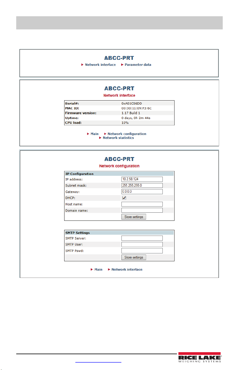
Configuring the network setting is done using a web browser or Anybus IP configuration utility
which can be downloaded from the Rice Lake Weighing Systems website.
To set the network settings using a web browser.
1. Open a browser and type the IP address of the card.
2. Change any or all settings.
3. Click on Store settings.
To set the network settings using the Anybus IP Configuration program.
1. Open the configuration program found on the CD.
2. Click on Scan button if the device does not display in the menu.
3. Double click on the device. A menu is displayed with the current network settings.
4. Change any or all settings.
5. Click on the Set button.
6. Change any or all settings and click on the Set button.
Inhaltsverzeichnis
Andere Rice Lake Aufnahmegeräte Handbücher


Beliebte Aufnahmegeräte Handbücher anderer Marken


Strymon
Strymon NIGHTSKY Bedienungsanleitung

Mitsubishi Electric
Mitsubishi Electric 16CH DIGITAL RECORDER DX-TL5000U Bedienungsanleitung

Tews Technologies
Tews Technologies TPMC465 Bedienungsanleitung

Honeywell
Honeywell Excel 50 Bedienungsanleitung

SeaLevel
SeaLevel COMM+8.LPCI Bedienungsanleitung

Arturia
Arturia AUDIOFUSE STUDIO Bedienungsanleitung


