Ricmotech AP-Xtreme Bedienungsanleitung

Page A-1
Revised: 9/1/2021
Last Edited by: FR
APX 1000+ Assembly Manual
AP-Xtreme
Sim-Racing Chassis
Master Assembly Guide
SECTION A: SlipSense Assembly
If you are not installing the SlipSense motion system
then please proceed to Section B

Page A-2
Revised: 9/1/2021
Last Edited by: FR
APX 1000+ Assembly Manual
Slide two C2-1 bolts into the bottom slot of one of the ET1 rails which will be the “driver’s” side of the cockpit. Mount
one vibration foot at each end of the rail and secure with N2 and W2 nuts and washers.
Slide four (or six, see note above) C2-1 bolts into the bottom slot of the other ET1 rail which will be the “transmission
tunnel” side of the cockpit. Mount one vibration foot at each end of the rail and secure with N2 and W2 nuts and
washers. Then mount the T7 mounting plate just behind the midpoint of the rail and extending toward the area
between the rails.
C2-1 x 6
N2 x 6
W2 x 6
If Installing Mini-Mite wheel,
mount optional 2nd T7 side-by -
side about 18 inches apart.
C2-1 x 2
N2 x 2
W2 x 2
ET1 Rails x 2
PF1
Rubber Foot x 4
(Other illustrations in manual
show older foot design)
N4-A Pre-Installed on
top slot

Page A-3
Revised: 9/1/2021
Last Edited by: FR
APX 1000+ Assembly Manual
Bolt one T1 end panel to the “Front” of the platform (the end where the pedals will be).
T1
H2-2 x 4
W2 x 4
Page A-4
Revised: 9/1/2021
Last Edited by: FR
APX 1000+ Assembly Manual
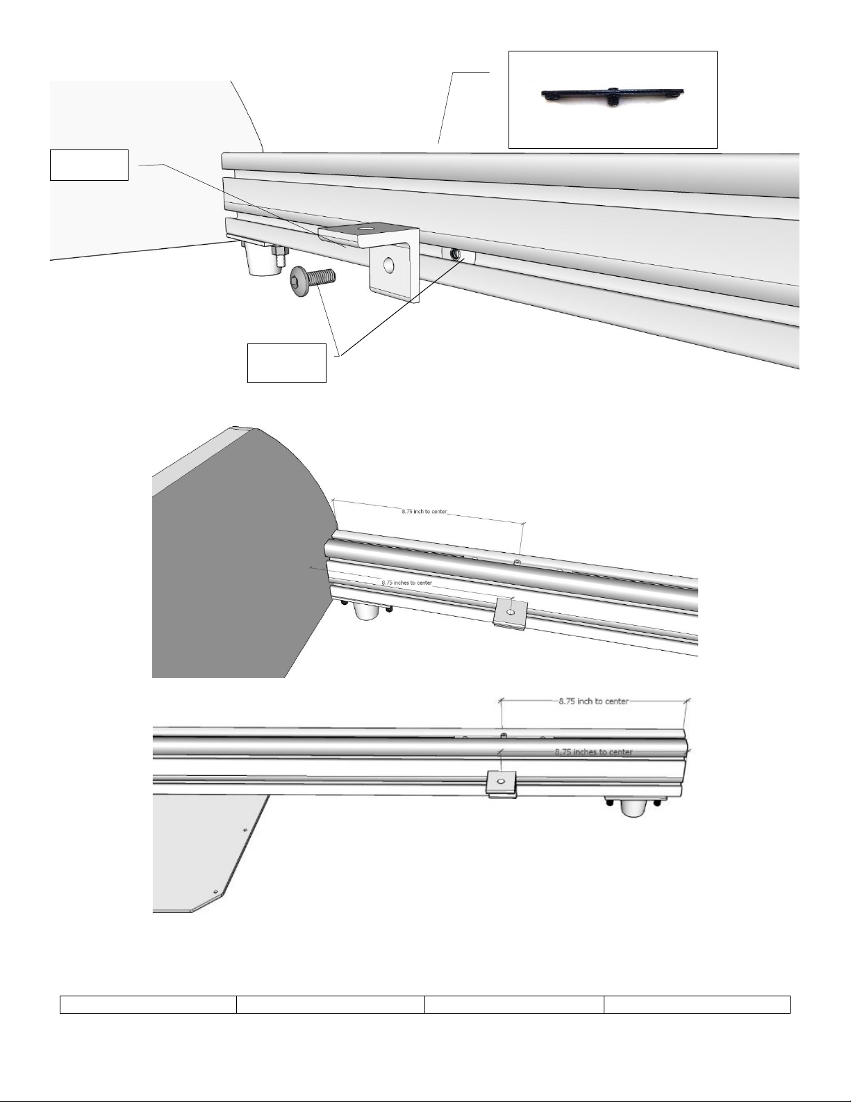
Mount two L1 angle brackets using the L2 hardware on the lower inner slot on each rail. Slide the nut into the end of the
ET1 rail with the flat side facing the bracket. Position each bracket 8.75 inches from the end of the ET1 rails as shown.
L2 x 4
L1 x 4
N4-A in top slot x 4
(may be pre-installed)

Page A-5
Revised: 9/1/2021
Last Edited by: FR
APX 1000+ Assembly Manual
Prepare the ET2 rails by inserting the N4-B insert and moving it to the exact center of the rail (may be pre-installed).
Tighten the 2 set screws to secure it in place. Insert one C2-2 into each end of the top slot and a C2-1 into each end of
the bottom slot.
Thread the bottom bolts into the angle brackets and secure in place with the W2 and N2 washers and nuts.
ET2 x 1
N4-B x 1
(May be Pre-Installed)
C2-2 x 2
C2-1 x 2
W2 x 4
N2 x 4

Page A-6
Revised: 9/1/2021
Last Edited by: FR
APX 1000+ Assembly Manual
Insert the R1-F roller and guard assembly onto the T2 panel as shown above. The guard is there to protect fingers and
toes from getting near the roller. DO NOT REMOVE THE GUARD!
Position the front roller mounts as shown at each side. These rollers will face up. Use bolts B2 in the outboard positions,
this change was made for safety reasons. The illustrations in the rest of the manual show the older bolts which are not
to be used here. The B2 bolts thread into the N4 nut inserts already installed.
T2 x 2
C2-2 x 2
W2 x 2
N2 x 2
R1-F x 2
B2 x 4
T2 x 2
R1-F x 2

Page A-7
Revised: 9/1/2021
Last Edited by: FR
APX 1000+ Assembly Manual
Mount the T3 platform over the rear rail as shown and secure with the indicated fasteners. Be sure to mount It with the
actuator notch facing downward. Use bolts B2 in the outboard positions, this change was made for safety reasons. The
illustrations in the rest of the manual show the older bolts which are not to be used here.
NOTE: The B2 bolt is used for safety reasons. The remainder of the manual illustrates the previously used bolt.
C2-1 x 4
C2-2 x 2
W2 x 2
N2 x 2
T3 x 1
Notch
Facing
Down
B2 x 4

Page A-8
Revised: 9/1/2021
Last Edited by: FR
APX 1000+ Assembly Manual
Attach the coupling to the actuator making sure the actuator cables exit pointing down. Do not overtighten the coupling.
Mount the actuator assembly to the bottom of the T3 platform with the coupling facing up as shown. Secure with T4
clamping block and six bolts, washers and nuts as indicated above.
NOTE: THE ACTUATOR PISTON SHIPS RETRACTED. DO NOT MANUALLY PULL ON IT. IT WILL EXTEND WHEN IT IS FIRST
CONFIGURED IN THE SOFTWARE.
N1 x 6
W1 x 6
C1-3 x 6
T4
SX1
Cable Exiting
at Bottom

Page A-9
Revised: 9/1/2021
Last Edited by: FR
APX 1000+ Assembly Manual
Insert the R1-R roller and guard assembly as shown on both ends of the T6 panel. The rollers should be positioned to roll
side-to-side. These rollers will face down. The guard is there to protect fingers and toes from getting near the roller. DO
NOT REMOVE THE GUARD!
The glider panel should roll side-to-side when the rollers are installed correctly.
R1 x 2
R1-R x 2
T6
R1 x 2
T6
R1-R x 2

Page A-10
Revised: 9/1/2021
Last Edited by: FR
APX 1000+ Assembly Manual
Install the C2-1 bolts shown above to the E1 rails for the main chassis. Position the eight A10 vibration mounts from each
end using the template provided (APX_RulerFront.pdf and APX_RulerRear.pdf) which can be downloaded from our
website or is included in the printed manual ahead of this section. Position the A1 plates and finger tighten, the exact
location will be determined later.
E1 from
the main
chassis
If installing real racing
seat slider brackets then
place 8 C2-1 bolts
as shown here.
A1 x 2
C2-1 x 4
W2 x 4
N2 x 4
from the main chassis
A10 x 8
(4 ship with SlipSense and 4
more ship with main chassis)
C2-1 x 16
W2 x 16
N2 x 16
Front
Andere Handbücher für AP-Xtreme
2


