Robe Anolis E-box Remote Basic Bedienungsanleitung

1
Version 1.6

2
E-box Remote Basic
Table of contests
1. Safety information ............................................................................................................... 3
2. Fixture description .............................................................................................................. 4
3. Mounting ............................................................................................................................. 6
4. Eminere Remote modes ..................................................................................................... 9
5. Technical specifications .................................................................................................... 13
6. Disposing of the product ................................................................................................... 14
7. Change Log ...................................................................................................................... 14

3
FOR YOUR OWN SAFETY, PLEASE READ THIS USER MANUAL CAREFULLY
BEFORE POWERING OR INSTALLING YOUR E-BOX REMOTE BASIC!
Save it for future reference.
1. Safety information
DANGEROUS VOLTAGE CONSTITUTING A RISK OF ELECTRIC SHOCK IS PRESENT WITHIN
THIS UNIT!
Make sure that the available voltage is not higher than stated on the fixture.
Always disconnect the fixture from AC power before removing its cover.
Make sure that the supply cables are not damaged by sharp edges. Check the fixture and the cables from
time to time.
Do not install the fixture near an open flame.
This fixture falls under protection class I. Therefore, this fixture has to be connected to a mains socket outlet
with a protective earthing connection.
Do not connect this fixture to a dimmer pack.
Do not cover the fixture with cloth or other materials.
The fixture is designed for outdoor use and it is intended for professional application only. It is not for
household use.
When choosing the installation spot, please make sure that the fixture is not exposed to extreme heat or dust.
Only operate the fixture after having checked that the housing is firmly closed and all screws are tightly fastened.
Operate the fixture only after having familiarized yourself with its functions. Do not permit operation by persons
not qualified to operate the fixture. Most damages are the result of unprofessional operation!
Please consider that unauthorized modifications on the fixture are forbidden due to safety reasons!
Please use the original packaging if the fixture is to be transported.
If this device will be operated in any way different to the one described in this manual, the product may suffer
damages and the warranty becomes void. Furthermore, any other operation may lead to dangers like
short-circuit, burns, electric shock etc.
Immunity of the equipment is designed for electromagnetic environments E1, E2, E3 according to the
standard EN55103-2 ed.2 Electromagnetic compatibility. Product family standard for audio, video, audiovisual
and entertainment lighting control apparatus for professional use. Part 2: Immunity.
The product (covers and cables) must not be exposed to a high frequency electromagnetic field higher than 3V/m
The installation company should check levels of possible interferences above the tested levels E1, E2, E3
given by this standard (e.g., transmitters in surrounding area) before installing the equipment.
Emission of the equipment complies with the standard EN55032 Electromagnetic compatibility of multimedia
equipment – Emission Requirements according to class B.

4
2. Fixture description
A - Top cover
B - Top cover screws
C - Mounting holes
1 - LED Output 1 (cable gland M20x1.5)
2 - LED Output 2 (cable gland M20x1.5)
3 - Power IN (cable gland M20x1.5)
4 - DMX IN (cable gland M12x1.5)
View
without
top
cover

5
Connection points
Detail of PCB

6
Fixture must be installed by a qualified electrician in accordance with all national
and local electrical and construction codes and regulations.
Setting and addressing the E-BOX REMOTE BASIC without top cover can be done
by a qualified person only!
ALWAYS DISCONNECT THE E-BOX REMOTE BASIC FROM MAINS BEFORE
CONNECTING/DISCONNECTING LED MODULES
This device falls under protection class I. Therefore, every E-box Remote Basic
has to be connected to a mains socket outlet with a protective earthing connection
3. Mounting
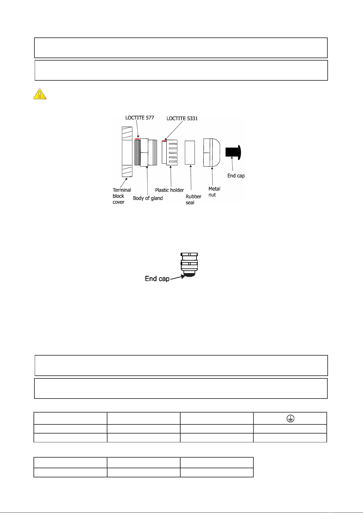
Note for cable glands.
We recommend applying an adequate layer of the paste LOCTITE 5331 on the plastic holder of the
cable gland before inserting it into the body of the gland and an adequate layer of the paste LOCTITE 577 on
the thread of the gland body.
1. Remove the top cover (A) from the E-box Remote Basic by unscrewing four fastening screws (B) in order to
get access to the terminal boxes.
2. Fasten the E-box Remote Basic on a non-flammable flat surface via four mounting holes (C) of
a diameter of 7 mm in its housing.
3. Remove end caps from cable glands before passing cables. To keep declared IP rating of the
device, every cable gland has to be covered with the end cap if the cable gland is not used.
5. Pass cable for DMX through cable glands M12x1.5 and connect it to the terminal block and tighten the
cable in the cable gland.
6. Pass cables for Power and LED outputs through cable glands M20x1.5 and connect them to the terminal
blocks and tighten the cables in the cable glands.
Cable glands serve for cables of the following diameters:
Cable gland M12x1.5 (DMX) - for cable of a diameter of 3-7mm.
Cable gland M20x1.5 (Power IN, LED Output) - for cable of a diameter of 7-13mm.
7. Check that all screws and cable glands are firmly tightened.
8. Screw the cover (A) back on the box.
Power connection
L N
Core (CE) Brown Blue Green/yellow
Core (US) Black White Green
DMX connection
D+ D- 0V
Data + Data - Data ground (shielding)

7
Terminator
Eminere Remote connection
Mark Function Wire
Vcc LEDs + Red
D+ DATA + Orange
D- DATA - Black
0V LEDS - White
Ground Not connected
Example of connection

8
Terminator
Terminator
Each line of Emineres Remote connected to the LED output of the E-box Remote Basic has to be terminated at
the last fixture.
EITHER connect a 120 Ohm resistor between terminals D+ and D- as shown, OR terminate via RDM as
described on page 11.
Ensure ONLY the last fixture in the line is terminated using ONE of the above methods!
The number of Emineres Remote connected to one LED output of the E-box Remote Basic depends on the
type of Eminere Remote and cable length.
The table states max. number of Emineres Remote connected to the E-box Remote Basic.
Max. number of Emineres Remote connected to the E-box Remote Basic
Cable length * Eminere Remote 1 Eminere Remote 2 Eminere Remote 3 Eminere Remote 4
25 m 20 10 6 5
50 m 16 8 5 4
75 m 13 6 4 3
100 m 10 5 3 2
* Cable length is the total cable length between E-box Remote Basic and last connected Eminere Remote.
Example: Total cable length=L1+L2+L3+L4
Max. number of Eminere Remote modules connected to the one output of the E-box Remote Basic is stated in the following
table.
Max. number of Emineres Remote connected to the one output of the E-box Remote Basic
Eminere Remote 1 Eminere Remote 2 Eminere Remote 3 Eminere Remote 4
16 8 5 4
Example: if you want to connect 20 Emineres Remote 1 to the E-box Remote Basic, you may connect 16 Emineres Remote
1 to output 1 and 4 Emineres Remote 1 to output 2 (at total cable length of 25 m).

9
4. Eminere Remote modes
The Emineres Remote can be operated in the two modes: Standard and Pass-Through. Switching to the modes
can be done by RDM.
Standard - LED modules are switched to an internal serial connection. DMX addressing of connected LED
modules is made automatically (default DMX address = 1, changes can be done by RDM). The Standard
mode is set as default.
Pass-Thr - LED modules are switched to an internal parallel connection. DMX addressing of connected LED
modules has to be done manually by means of the Robe Universal Interface (or its wireless version Robe Uni-
versal Interface WTX) and the software RDM Manager.
Note: RDM Manager and DMX controller cannot be connected at the same time.
Terminator
Terminator

10
Examples of RDM manager screenshots for one connected LED module.
Initial screen of the RDM manager:
Click on the device to show
options of the Control panel
Options in the Control panel allows you to set DMX address and Personality for each LED module.
Click on the green
arrow to save
adjusted values
DMX preset and
number of used
channels.
DMX address
Note:
If only Emineres Remote 1 are connected to
the E-Box Remote Basic, there is no
difference between DMX Preset 1 (fixture
mode) and DMX Preset 2 (pixel mode).
Occupied channels are displayed in the window DMX patch on the right side of the Control panel.
Andere Handbücher für Anolis E-box Remote Basic
2
Inhaltsverzeichnis
Andere Robe Fernbedienung Handbücher
Beliebte Fernbedienung Handbücher anderer Marken

Panasonic
Panasonic EUR7622KB0 Bedienungsanleitung

Bang & Olufsen
Bang & Olufsen Beo4 Bedienungsanleitung

Sunwave Tech.
Sunwave Tech. RemoteComm SRC-7000 Bedienungsanleitung

Multiplex
Multiplex PROFI TX 9 Bedienungsanleitung

One Remote
One Remote RMB4 Bedienungsanleitung

FUTABA
FUTABA 9ZAP - PART2 Bedienungsanleitung