
Romac Transmate TapMate Bedienungsanleitung

a division of Romac Industries, Inc.
OPERATING MANUAL
Thank you for your purchase of the TapMate™XL 424 Pipe Drilling Machine.
Please read and understand this operation manual. Our goal is to serve you, our customer.
If you have any questions, complaints or improvement suggestions please call us at 1‑800‑426‑9341.
06/19/2019
TAPMATE™XL 424
Pipe Drilling Machine

TAPMATE™XL 424 OPERATING MANUAL
2
TABLE OF CONTENTS
Specication .......................................................................................................... 3
Machine Overview ................................................................................................. 4
ASSEMBLY
Open the Shipping Crate ...................................................................................... 5
CutterandPilotIdentication................................................................................ 6
About Adapter Hub Sizes ...................................................................................... 7
Adapter Hub Installation and Removal.................................................................. 8
TapMate XL‑424 Set‑Up for 4"‑12" Taps ............................................................. 10
TapMate XL‑424 Set‑Up for 14"‑24" Taps ........................................................... 14
Attaching the TapMate XL‑424 to the Valve ........................................................ 18
OPERATION
Performing the Tap .............................................................................................. 21
Disassembly and Removal of the Coupon........................................................... 26
Care and Maintenance......................................................................................... 27
PARTS IDENTIFICATION DRAWINGS
TapMate XL‑424 (included items) ........................................................................ 28
TapMate XL‑424 (base machine).......................................................................... 29
Adapter Bells (4" ‑ 12")........................................................................................ 30
Adapter Bells (14" ‑ 24")...................................................................................... 31
Adapter Hubs ...................................................................................................... 31
Small Shaft Head Assembly ................................................................................. 32
Large Shaft Head Assembly................................................................................. 32
Jam Nut ............................................................................................................... 32
TM‑XL, PVC Pilot.................................................................................................. 33
TM, PVC Pilot....................................................................................................... 33
TM‑XL, Shaft Nose............................................................................................... 34
TM, Shaft Nose .................................................................................................... 34
Hydraulic Motor Assembly................................................................................... 35
Shipping Crate / Workstation .............................................................................. 35

TAPMATE™XL 424 OPERATING MANUAL
3
• Heavy duty steel construction.
• Hydraulic motor integrated to shaft and machine.
• Weight of the TapMate XL‑424 is 285 lbs. (less the Adapter Bell, Pilot Drill and Cutters).
• Maximum length of the TapMate XL‑424 only is 87” (less the Adapter Bell, Pilot Drill and
Cutters).
• Cutter travel distance is 39".
• For use with 4" ‑ 24" cutters on 4" ‑ 24" dry or hot taps.
• Suitable for use on Cast Iron, Ductile Iron, Asbestos/Cement, Steel, PVC and HDPE pipe.
• 300 psi pressure rating.
• Compatible with TapMate and or QuikValve Adapters, Cutters and Shaft Noses and PVC
Pilots.
• External components of the TapMate XL‑424 are QPQ heat treated for protection from
wear and corrosion.
• Manual feed provides control and feedback during the cut.
• Thrust Tube Thread is a #2 Stub Acme Thread for rapid and controlled travel through the
Valve and Tapping Sleeve Neck.
• Thrust Tube features a scale to indicate the amount of travel.
• Indicator Scale on the Lead Tube shows the exact Cutter depth and progress of the cut.
• Input torque limit: Continuous = 3,604 in‑lbs., Intermittent = 4,283 in‑lbs.
• Input RPM: 33.
TAPMATE™ XL-424 MACHINE SPECIFICATION
TAPMATE™XL 424 OPERATING MANUAL
4
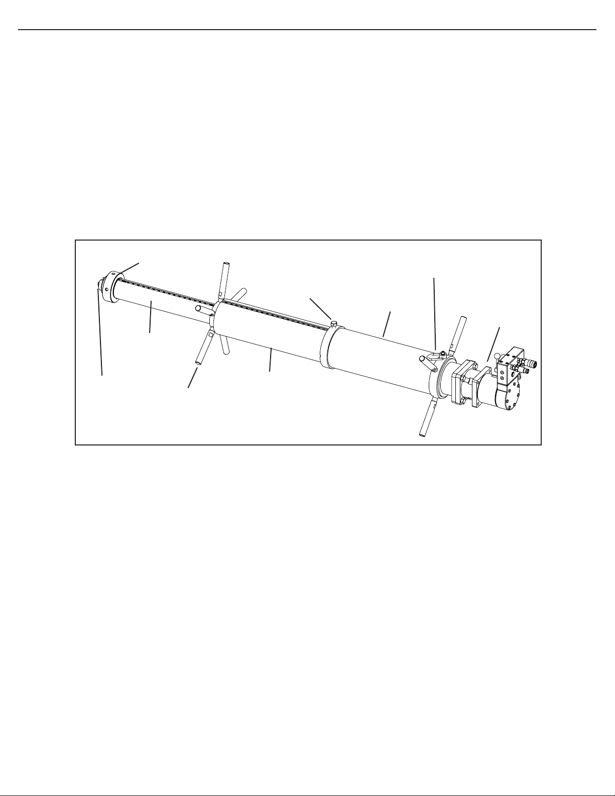
MACHINE OVERVIEW
While you may be familiar with the TapMate drilling machine, the TapMate XL‑424 is
larger and has different operating requirements. These include:
• The TapMate XL‑424 has no sliding Tubes or Brakes.
• Fewer turns are required to complete the tap (in most cases).
• TapMate XL‑424 feed rates are slower due to the ACME threads.
The TapMate XL‑424 drilling machine consists of four distinct sections. These sections
are the Shaft, Lead Tube, Thrust Tube and the Brake Tube.
The threaded Thrust Tube is located in the center of the machine and the Brake Tube
is positioned toward the back of the machine. Together, they control travel of the Shell
Cutter and Pilot Drill. Prior to the cut, the Shell Cutter and Pilot Drill are extended
through the valve and tapping sleeve neck to the pipe wall using the Brake Tube Han‑
dles. After the cut is complete, the Shell Cutter and Pilot Drill retract through the valve
to allow the valve to be operated.
After the tap is completed and you are drawing the Cutter away from the Pipe, the Brake
Tube thread prevents water pressure from turning the Brake Tube.
The Lead Tube and Lead Nut are located inside the front end of the Thrust Tube. To‑
gether, they provide the forward pressure necessary for the Pilot Drill and Shell Cutter
during the cutting operation.
The Shaft is a single piece running through the center of the Machine. It is threaded on
the front end to accept the Pilot Drill and Shell Cutter. The other end of the Shaft mates
with the Hydraulic Drive Unit.
Lead Tube
Thrust Tube
Brake Tube
Shaft
Lead Nut
w/Handles
Brake Locking Bolt
Rear Lifting Ring
Locking Collar
Integrated
Hydraulic
Drive
g. 1

TAPMATE™XL 424 OPERATING MANUAL
5
v. 1.3
OPEN THE SHIPPING CRATE/WORKSTATION
3. Lift and remove Cover (see g. 3).
1. Open all (six) of the latches around bottom of the
Crate.
2. Swing open the End (see g. 2).
g. 2
g. 3

TAPMATE™XL 424 OPERATING MANUAL
6
CUTTER AND PILOT IDENTIFICATION
1. Select the proper Cutter and Pilot for the pipe you'll be tapping (see g. 4 & 5).
70;/6+$)7126(
7$36
70;/6+$)7126(
7$36
7<3,&$/&$5%,'(&877(5'(6,*1
7<3,&$/&$5%,'(&877(5'(6,*1
&XWWHUDQG3LORWVVKRZQEHORZDUHIRUXVHRQ'XFWLOH,URQ&DVW,URQDQG$VEHVWRV&HPHQWSLSH
706+$)7126(
7$36
TM-XL, PVC PILOT
(14" - 16" TAPS)
TM-XL, PVC PILOT
(18" - 24" TAPS)
4" - 12"
TYPICAL PVC CUTTER DESIGN
TM, SHAFT NOSE
(4" - 12" TAPS)
g. 4
g. 5
Cutter and Pilots shown below are for use on Ductile Iron, Cast
Iron and Asbestos/Cement pipe.
Cutter and Pilots shown here are for use on PVC pipe.
NOTE: USE CARBIDE CUTTER PER FIG. 4 FOR 14” THRU 24” CUTS

TAPMATE™XL 424 OPERATING MANUAL
7
ABOUT ADAPTER HUB SIZES
1. Ensure that the correct Adapter Hub is securely attached to the Lead Tube.
TodeterminewhichAdapterHubyou'llneed,seeg.6below.
Small Adapter Hub
for use with
4" ‑ 12" TapMate Adapter Bells.
Large Adapter Hub
for use with
14" ‑ 24" TapMate XL‑424
Adapter Bells.
NOTE: The TapMate XL-424 is shipped from the factory
without an Adapter Hub installed.
g. 6

TAPMATE™XL 424 OPERATING MANUAL
8
ADAPTER HUB INSTALLATION AND REMOVAL
Large Adapter
Hub Keyway
Keyway
Lead Tube
Locking Collar
Small Adapter
Hub
Installation:
1. Select the appropriate Adapter Hub for the size
of Adapter Bell to be used (Small Adapter Hub
for 4"‑12" and Large Adapter Hub for 14"‑24").
2. Align the Keyway in the Adapter Hub with the
Key in the top of the Lead Tube (see g. 7).
3. Slide Adapter Hub over the end of the Lead
Tube and engage the threads of the Lead Tube
Locking Hub Collar (see g. 8).
Large Adapter
Hub
Small Adapter
Hub
g. 7
g. 8

TAPMATE™XL 424 OPERATING MANUAL
9
ADAPTER HUB INSTALLATION AND REMOVAL (cont.)
4. Tighten with a Spanner Wrench.
Removal:
1. Unscrew the Adapter Hub from the Lead
Tube Locking Collar with the Spanner
Wrench.
2. Slide the Adapter Hub off the Lead
Tube and store in Shipping Crate / Work
Station.
Large Adapter HubSmall Adapter Hub
Large Adapter HubSmall Adapter Hub
g. 9
g. 10

TAPMATE™XL 424 OPERATING MANUAL
10
1. After the Small Adapter Hub has been securely
attached to the Lead Tube, check the neck of the
TapMate Adapter Bell to be sure that the O‑ring is
present.
2. Screw the appropriate size and style Adapter Bell
onto the end of the Adapter Hub. You should feel
theO-ringcompressasyounishthreadingitinto
the Adapter Hub (see g. 11).
5. Remove the Brake Tube Locking Bolt from the Brake
Tube (see g. 13). This will allow the Brake Tube to
rotate separate from the entire machine. Remove the
back Workstation Brace. Leave the Front Workstation
Brace in place.
3. There are four Set Screw Holes around the Neck of
the Adapter Bell. Continue to thread the Adapter on
until the next Hole is over the Flat Slot on the top of
the Hub.
4. Insert one Set Screw into the Hole located above the
Flat and use a 3/16" Allen Wrench to tighten the Set
Screw (see g. 12).
NOTE: The Set Screw must bear ENTIRELY on
the Flat of the Small Adapter Hub. Otherwise, damage
to the threads of the Hub under the Set Screw may oc-
cur, which in turn will make the Adapter Bell very difcult
to remove. Further damage to the threads of the Adapt-
er Bell may also occur as you unscrew it from the Hub.
Small
Adapter
Hub
Adapter Bell
(4" ‑ 12")
Set Screw
Brake Tube
Locking Bolt
Workstation
Rear Brace
TAPMATE XL-424 SET-UP FOR 4"-12" TAPS:
For instructions on attaching the Large Adapter Bell (for 14"-24" taps),
turn to page 14.
g. 11
g. 12
g. 13
Dieses Handbuch passt für folgende Modelle
1
Inhaltsverzeichnis


