Ryonet RCJ21-3500 Bedienungsanleitung

RCJ21-3500
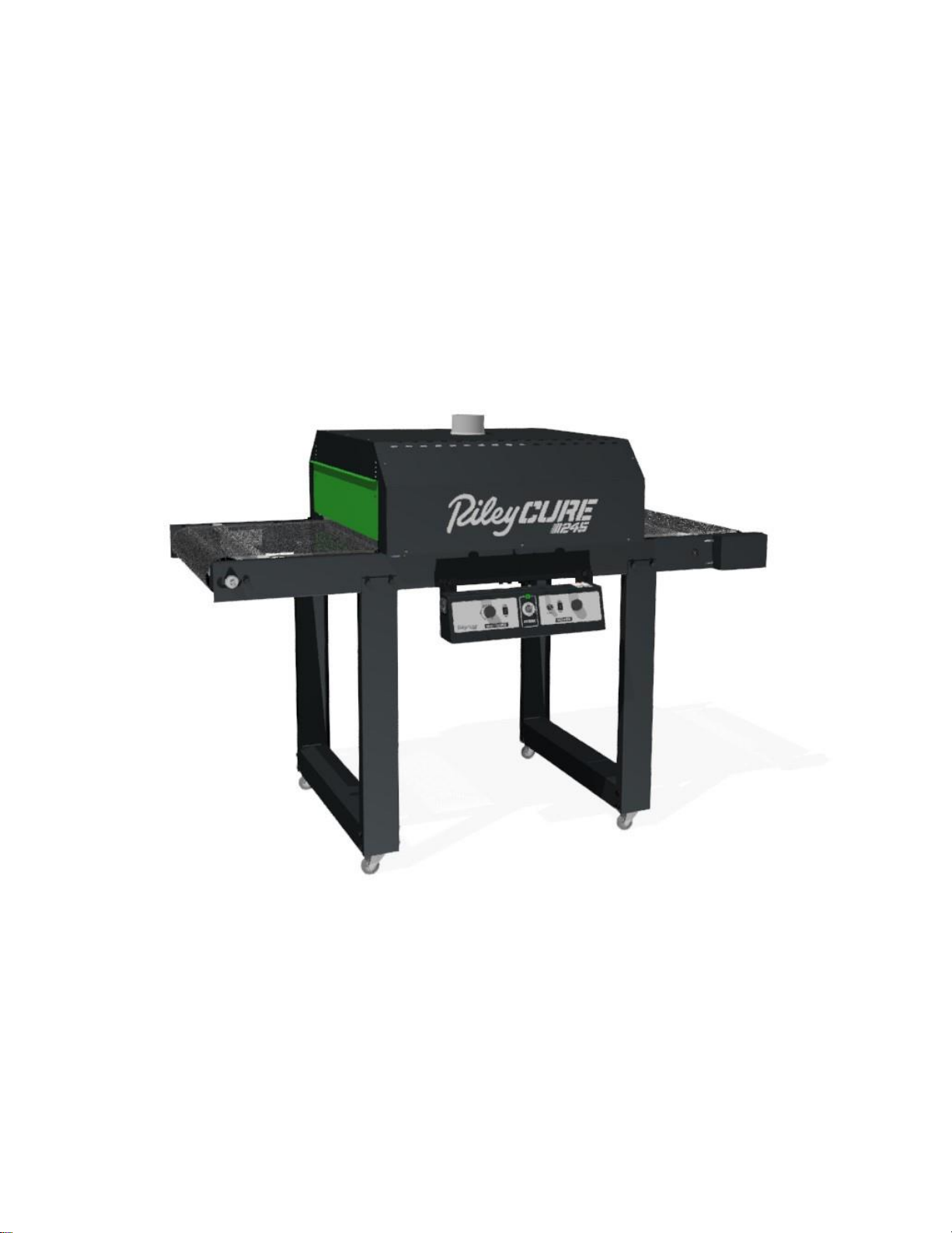
Conveyor Dryer
24” wide by 5’ long conveyor dryer
Document # 16-514
Serial Number: _______________________________ Date: ___/___/________
(Record your machine’s serial number and date of purchase for future reference)

IMPORTANT INSTRUCTIONS:
Read all these instructions before installing or using this equipment.
All wiring to this equipment must be connected to the electrical source in strict accordance with
National Electrical Code (N.E.C.) and local codes having jurisdiction.
Do Not use extension cords to power this equipment.
Before installing this equipment, the user must be aware of the safety requirements as specified
by the National Fire Protection Association (NFPA).
CAUTION: Puncture of the element face may result in a shock hazard.
This heater is hot when in use. To avoid burns, do not let bare skin touch hot surfaces. Keep
combustible materials, such as furniture, pillows, bedding, papers, clothes, etc. and away from
the dryer.
Extreme caution is necessary when any dryer is used by or near children or disabled persons
and whenever the heater is left operating and unattended.
Do not operate any heater after it malfunctions. Disconnect power at service panel and have
heater inspected by a reputable electrician before reusing.
Do not use outdoors.
To disconnect dryer, unplug from power source or turn off power to dryer circuit at main
disconnect panel.
Do not insert or allow foreign objects to enter any ventilation opening as this may cause an
electric shock or fire, or damage to the dryer.
A dryer has hot and arcing or sparking parts inside. Do not use it in areas where gasoline,
paint, or flammable vapors or liquids are used or stored.
Use this dryer only as described in this manual. Any other use not recommended by the
manufacturer may cause fire, electric shock, or injury to persons.
SAVE THESE INSTRUCTIONS

Assembly and Operating Instructions
RETAIN THIS MANUAL FOR FUTURE REFERENCE
Please review these instructions prior to assembly.
The Riley Cure 245 is packaged in 5 cartons for shipment.
Please make sure all pieces have been received before attempting assembly.
Tools Required: One ½” wrench & needle nose pliers
Label on Box
Qty
Contents
RCJ21-D &
RCJ21-T
1
1
Drive half of Conveyor Bed, with motor
Take Up half of Conveyor Bed
RC21-LK
4
2
4
30
Conveyor Legs
Leg Cross Braces
Caster Assemblies
Bolts
RC14-301
1
Conveyor Belt
RCJ21-CP-240
1
Control Panel
RCJ21-3500C
1
1
1
1
2
Assembly Instructions
Heating Chamber
4-inch Duct Start Collar
4-inch Duct 2 feet long
End Shield
WARNING!
Note:DO NOT plug the equipment in (or apply power) until instructed to do so.
Note:The Riley Cure 245 requires a dedicated 240 Volt, 20 Amp circuit. Any
attempt to operate the Riley Cure 245 without the cord/plug provided by the
manufacturer will void the warranty.
Accessories available:
•90-409 Motor Cord (For Control Panel Assembly Opposite Side)
Note:Portions of the assembly procedure require 2 people.
Unpack, identify, and inspect all parts. Report any missing or damaged items.
Cover a 4’ x 9’ area on the floor with towels, cardboard, carpet, etc. to protect the
painted parts from being scratched during assembly.

Conveyor Bed Assembly:
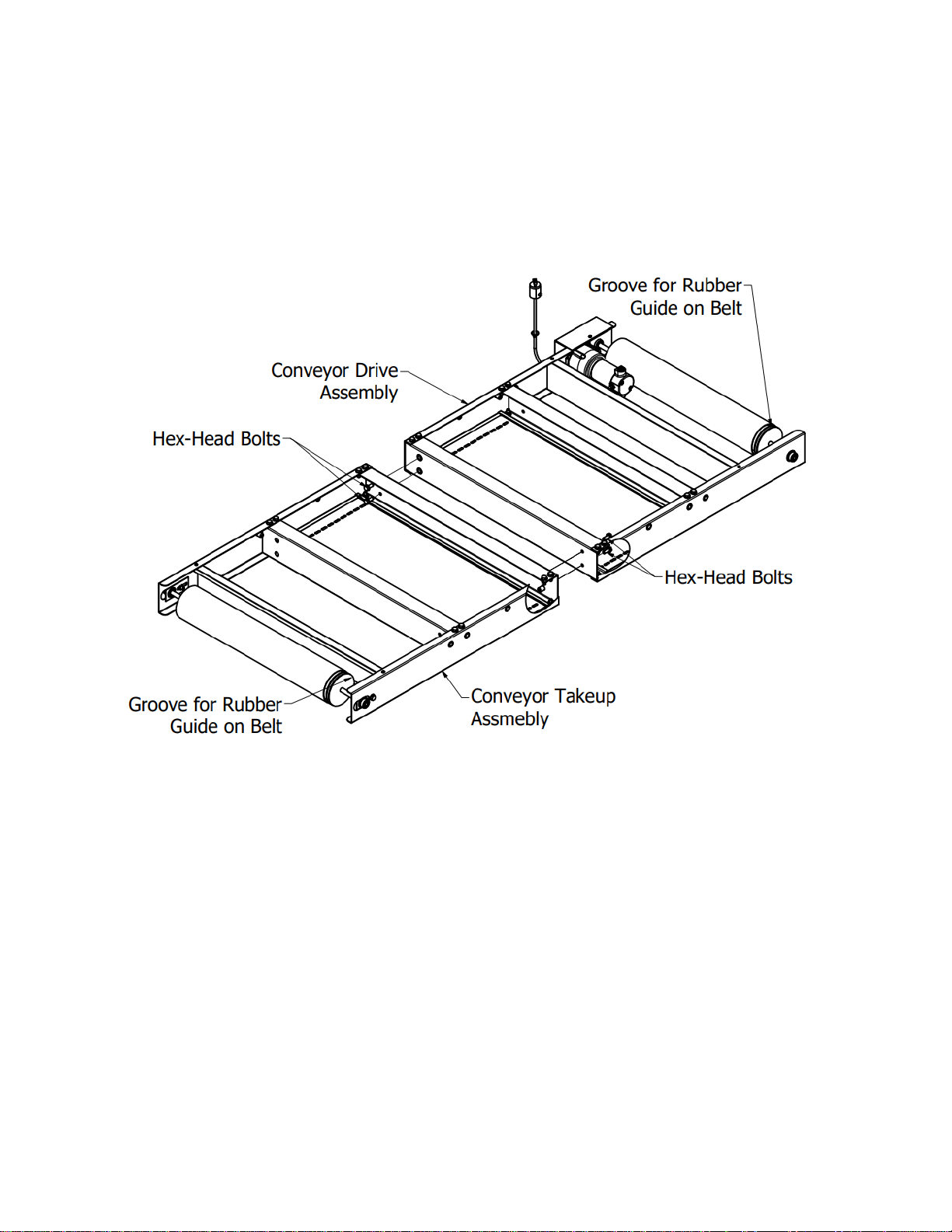
1. Remove (4x) Hex-Head Bolts from RC21-LK carton.
2. Place the Conveyor Drive Assembly on the covered floor (See Figure 1).
3. Butt the Conveyor Take-Up Assembly to the Drive Assembly. Be sure that the
groove on each roller drum is on the same side of the bed.
4. Bolt the bed assembly together using (4x) Hex-Head Bolts.
Figure 1
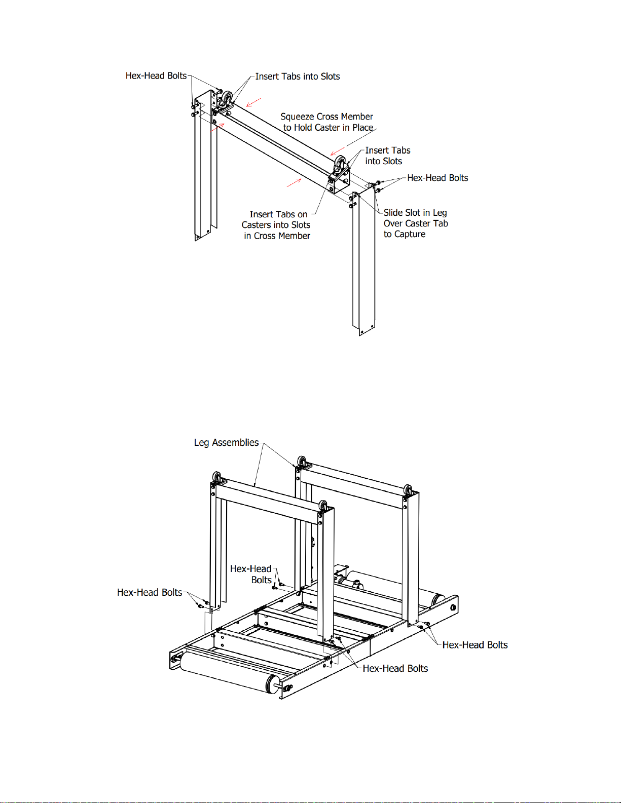
5. Insert the Tabs on the Caster Assembly into the slots on the Leg Cross Brace, then
squeeze the Cross Brace to hold the Caster in place (See Figure 2).
6. Slide the Leg over the end of the Leg Cross Brace seating the slot in the Leg to
capture the Tab on the Caster.
7. Align the thru-holes with the insert nuts and install the Hex-Head Bolts.
8. Repeat for the four Caster Assemblies, completing the two Leg Assemblies (See
Figure 2).

Figure 2
9. Place the Leg Assemblies over the Conveyor, aligning the thru holes of the Leg
Assemblies with the insert nuts of the Conveyor.
10.Install the eight Hex-Head Bolts (See Figure 3).
Figure 3

11.Tighten all Bolts.
12.Using two people turn the conveyor bed over onto its casters.
Conveyor Belt Installation:
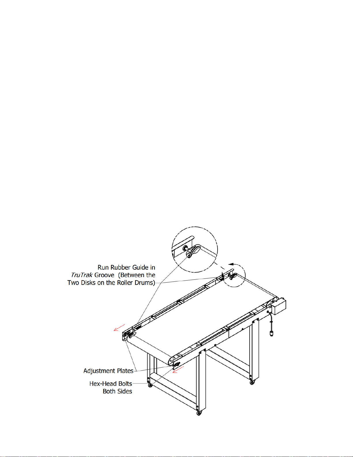
1. Determine the side of the belt that will convey product. A rubber guide is stitched
onto one edge of the belt. This guide is designed to ride in the TruTrak™roller drum
grooves to provide hassle free tracking (See Figure 4).
2. Carefully remove the splice pin from the inside teeth of the splice connector by
pulling gently with needle nose pliers if needed. DO NOT BEND; this pin will be
reinserted later.
3. Lay the belt on the conveyor bed aligning the edge guide with the roller drum
grooves.
4. Pull the ends of the belt together meshing the teeth of the splice while a second
person reinserts the splice pin (removed earlier) into the channel formed by the
interlocked metal teeth. It may be easier to rotate the belt so that the splice is on top
of the conveyor bed before inserting pin. Using needle nose pliers, fully insert the
pin until it is centered.
5. Adjust belt tension: Loosen (2x) hex bolts at Take Up Roller (See Figure 4). Pull
roller at groove end till you have sag of 1 –1.5 inches below the cross-members as
the belt travels under the conveyor bed. Over-tightening the belt can lessen the
lifetime of the conveyor belt. Tighten hex bolt.
6. Adjust opposite end of roller to same location and tighten hex bolt.
Figure 4

Control Panel Installation:
1. Using two Hex-Head Bolts to fasten the Control Panel to the Conveyor Assembly
(See Figure 5).
Figure 5
2. Insert drive motor plug into drive motor receptacle. Twist plug to lock in place (See
Figure 6).
Figure 6

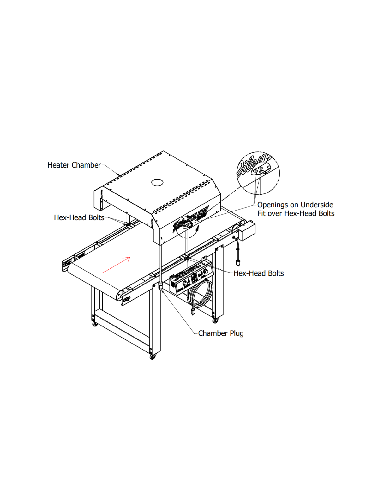
Attaching Heating Chamber:
1. Using two people set the chamber onto the conveyor bed (See Figure 7). The
Heating Chamber Cord must be on the same side of the Conveyor Bed as the
Control Panel.
2. The Heating Chamber has openings on the underside rails that fit over the hex-head
bolts (See Magnified View, Figure 7). The chamber should rest flatly on the
conveyor bed.
Figure 7
3. Insert the Duct Start Collar into the hole in the top of the Heating Chamber (See
Figure 8). Once in position, bend the tabs at the base of the collar outward to
secure it in place. Place the two-foot section of 4” diameter Duct onto the Duct Start
Collar.
4. Place End Shields at desired height on the entrance and exit of the Heating
Chamber.
5. Plug the Heating Chamber cord into the receptacle on the Control Panel (See
Magnified View, Figure 8).

Figure 8

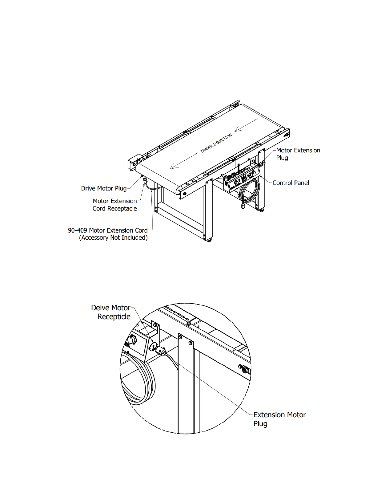
Control Panel Installation Opposite Side: (90-409 Extension Cord Sold Separately)
1. Using two Hex-Head Bolts to fasten the Control Panel to the Conveyor Assembly
(See Figure 9).
Figure 9
2. Insert Drive Motor Plug into Motor Extension Cord Receptacle. Twist plug to lock in
place (See Figure 9). Insert Motor Extension Cord Plug into Drive Motor
Receptacle. Twist plug to lock in place (See Figure 10).
Figure 10
Inhaltsverzeichnis
Beliebte Trockner Handbücher anderer Marken

Indesit
Indesit IDV 75 Bedienungsanleitung

Infiniton
Infiniton SD-DG85C Bedienungsanleitung

BOMANN
BOMANN WT 5019 Bedienungsanleitung

Alliance Laundry Systems
Alliance Laundry Systems TMB795C Bedienungsanleitung

Asko
Asko T793C Bedienungsanleitung

Kenmore
Kenmore 8041 - 5.8 cu. Ft. Capacity Electric Dryer Bedienungsanleitung