
S.E.A. Group RESCUE Intellitech DeconFilter Pro S Bedienungsanleitung
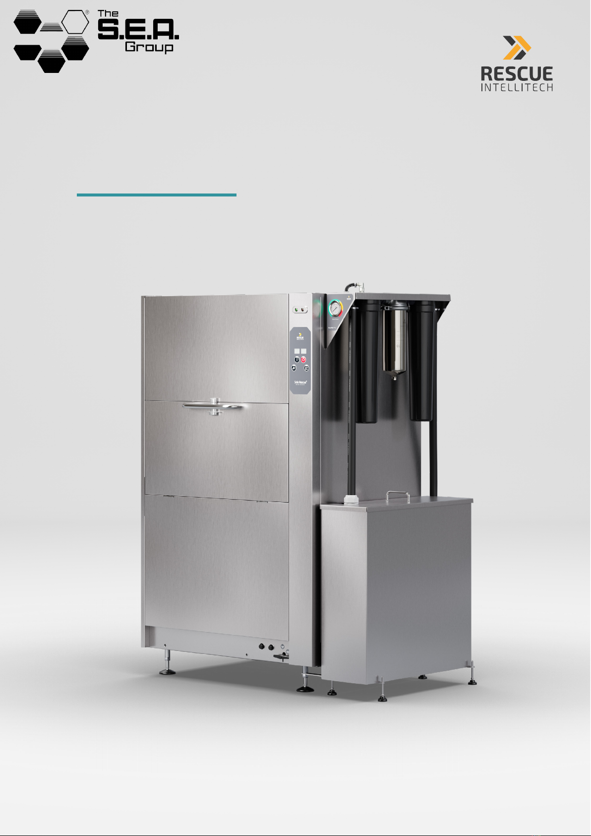
Installation, user instructions and service
DeconFilter™ Pro S – Manual

2
Content
2 General Description and Safety 4
2.1 To the user 4
2.2 Safety regulations 4
2.3 Limited Warranty 4
2.4 Limitation of Liability 5
3 Technical data 5
3.1 Installation drawing 6
3.1 Installation drawing – Wall Mount 6
4 Installation 7
4.1 Mounting the filter rack 7
4.2 Pressure gauge 9
4.3 Tank installation 9
4.4 Filter cartridge installation 13
5 Operation 13
6 Service & Maintenence 14
6.1 Filter change interval 14
6.2 Replacement Cartridges 15
6.3 Replacement of Filter Cartridges 15
6.4 Cleaning 15
7 Spare parts list 17

4
2 General Description and Safety
2 General Description and Safety
2.1 To the user
The DeconFilter™ Pro S is designed with the express purpose of being used together with the Solo Rescue®
Decon Washer and shall not be used in any other context. It serves the purpose of filtering the contaminated
wash water from the Solo Rescue before flushing it out the drain.
This manual is your guide to the correct use of the DeconFilter™ Pro S.
RESCUE Intellitech recommends that you study the manual thoroughly to be sure that the filter system is used
correctly and safely.
Ensure that the manual is always available throughout the service life of the filter system.
RESCUE Intellitech disclaims any and all liability for any damages or injury to persons, property or otherwise
resulting from misuse or failure to follow instructions found in this Manual, failure to wear hand and face
protection when changing filter cartridges, and or replacing filters with cartridges that are not supplied by
RESCUE Intellitech or their appointed representatives.
2.2 Safety regulations
Scalding risk. The DeconFilter™ Pro S may contain hot, contaminated water. It may contain hazardous toxic
chemicals and carcinogens.
During filter changes and while performing service and maintenance...:
•...always wear eye protection
•...always wear protective gloves
•...always make sure the filter system is powered o by disconnecting the DeconFilter™ Pro S from the
electrical socket.
•...all use of the connected Solo Rescue®Decon Washers is prohibited.
2.3 Limited Warranty
RESCUE Intellitech warrants and represents that all of its products are free of defects in materials or
workmanship for a period of twelve (12) months from the date of delivery, subject to normal wear and tear and
provided that the relevant DeconFilter™ Pro S has been used in accordance with the instructions, manuals and
guidelines provided by RESCUE Intellitech (as amended from time to time).
In the event that a DeconFilter™ Pro S delivered by RESCUE Intellitech would not meet the requirements
under said limited warranty (that is, there would be a defect in materials or workmanship as shown within
a period of twelve months from the date of delivery), RESCUE Intellitech shall at its own cost and expense
either (i) redeliver the relevant DeconFilter™ Pro S (upon receipt of the defective product from the dealer and
confirmation of the defect) or (ii) remedy the relevant defect. RESCUE Intellitech shall, at its own discretion,
choose either one of remedy (i) or (ii).
Except for the limited warranty expressly stated above, neither RESCUE Intellitech nor any of its
representatives or aliates make any express or implied representation or warranty or condition with respect
to any DeconFilter™ Pro S or any other products delivered. RESCUE Intellitech disclaims any and all other
representations, warranties and conditions in any form whatsoever, whether express or implied, including
5
2 General Description and Safety
without limitation, the implied warranties of merchantability, title and/or fitness for a particular purpose.
The express limited warranty above is ONLY valid if the DeconFilter™ Pro S is installed by an authorized
representative of RESCUE Intellitech. If a DeconFilter™ Pro S would be installed, repaired or otherwise
modified by someone other than an authorized representative of RESCUE Intellitech, the limited warranty shall
immediately lapse.
2.4 Limitation of Liability
In no event shall RESCUE Intellitech, or any of its representatives or aliates, whether in contract, tort or
otherwise, be responsible or liable for any consequential, indirect, incidental, special, exemplary, or punitive
damages arising out of or in connection with the delivery of any DeconFilter™ Pro S products, or the use
thereof, regardless of (a) whether such damages were foreseeable, or (b) whether or not RESCUE Intellitech
was advised of the possibility of such damages.
Except for obligations to make payment under this agreement, each party’s aggregate liability arising out of or
related to this agreement, whether arising out of or related to breach of contract, tort (including negligence) or
otherwise, shall not exceed the total amount paid under this agreement during the 12-month period preceding
the event giving rise to the claim.
The limitations of liability set out herein shall not apply with respect to damages arising out of grossly negligent
acts or omissions or wilful misconduct or misuse.
3 Technical data
Dimensions H x W x D 1800 x 300 x 750 mm (71’’ x 12’ ’x 30’’)
Weight (empty) 70 kg (154 lbs)
Filer tank volume 130 liters (34 gallons)
Power supply EU: 5 m (16 ft) cable with Schuko plug included. Other regions: Please contact your local dealer
Rated Voltage 220–240 VAC single phase
Fuse 10 A
Frequency 50 Hz
Rated Power 0,55 kW (0.7 hp)
Drain hose connection 19 mm (3/4”), 6m (19 ft) hose included
Minimum drain capacity min. 35 l/min (9 gallons/min)
Drain outlet height on wall max. 1,5 m (5 ft)
Filtration technology Multi stage custom filtration including lint filter, particle filters and active carbon filter
Pump Stainless steel, high temp, handle solids up to 10 mm (0.4’’).
Capacity Up to 3 Solo Rescue Decon Washers
Options Wall mount accessory
Filter change recommendation Every three months, or according to pressure indicator. More often depending on application.
6
3 Technical data
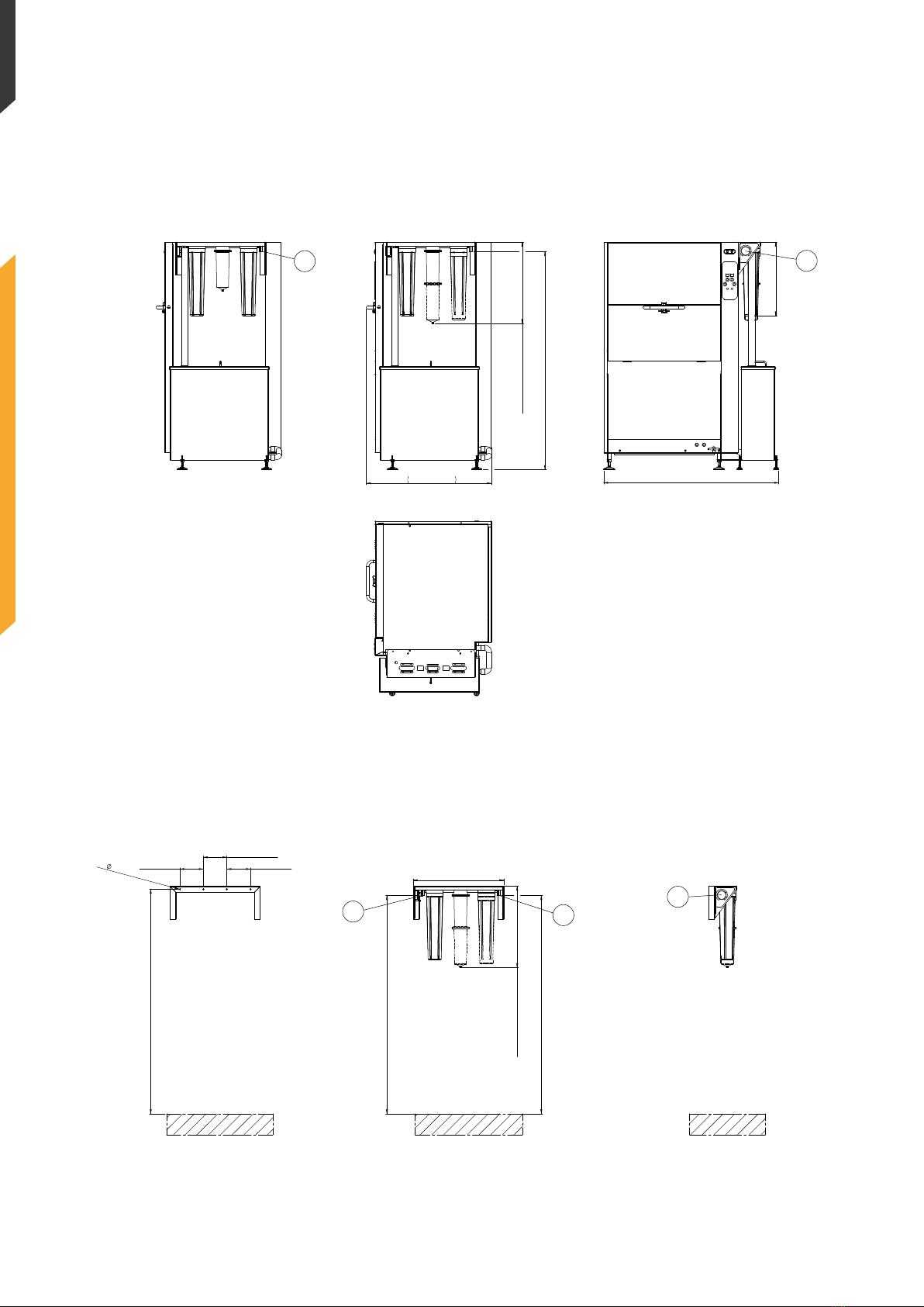
3.1 Installation drawing
A. Drain outlet/hose connection B. Pressure gauge
3.1 Installation drawing – Wall Mount
A. Inlet B. Drain outlet/hose connection C. Pressure gauge
565 mm / 22,3"
1340 mm / 52,8"
1/2
Checked By
and it is to be returned promtly upon request to GR ANULDISK AB.
This drawing contains confidential information and is the property
of GRANULDISK A B whithout whose permission it m ay not be
2021-10-19
Date
A2
Checked Date
1:10
0
Edition
Designed by Scale
Drawing number
Filter_Install
Sheet
copied, shown or handed to a third party or otherwise used,
GIS number
A2
Status Projection method
Additional Information
Outlet, depends on setting of machine feet
1670 mm / 65,8"
Decon washer max
955 mm / 37,6"
625 mm / 24,6"
Free space for filter exchange
695 - 1715 mm
27,4" - 67,5"
A2
Projection method
Checked DateChecked By Scale
Date
This drawing contains confidential information and is the property
and it is to be returned promtly upon request to GR ANULDISK AB.
of GRANULDISK A B whithout whose permission it m ay not be
Filter_Install
2021-10-19
1:10
0
Edition
Designed by Status
Drawing number
copied, shown or handed to a third party or otherwise used,
Sheet
2/2
GIS number
A2
Additional Information
Mounting of wall bracket
- Floor Level -
180 mm / 7"
180 mm / 7"
180 mm / 7"
4x 8 mm/ 0,32"
650 - 1670 mm
Not lower than drain
690 mm / 27,2"
Inlet (Dep. on mounting height)
Outlet (Dep. on mounting height)
25,6" - 65,8"
650 - 1670 mm
25,6" - 65,8"
625 mm / 24,6"
Free space for filter exchange
C
B
A
A
B

7
4 Installation
4 Installation
4.1 Mounting the filter rack
For filters mounted on the Solo Rescue –
go to section 4.1.1
For wall mounted filters – go to section 4.1.2
(Option, accessory needed)
4.1.1 Mounted on the Solo Rescue®
NOTE: Not applicable for Solo Rescue® 32-series,
use wall mount accessory instead. See section 4.1.2.
1. Unscrew the bolt holding the top cover on the
right side of the Solo Rescue® (Fig. 1)
2. Position the filter rack pins in the holes as
displayed in (Fig. 2)
3. Fasten the previously unscrewed bolt to fix the
filter rack on the Solo Rescue® (Fig. 3)
Figure 1
Figure 2
Figure 3

8
4 Installation
4.1.2 Mounted on the wall
Use wall mount accessory article number 27305.
IMPORTANT NOTE: Use suitable fastening (screws
and plugs) based on the construction of the wall
(not included in kit). Filter racks in operation weigh
approximately 30 kg (66 Ibs).
1. Remove the filter rack securing bolts (Fig. 4).
2. Make sure the wall mount is level. If drilling is
needed, make sure to mark where as displayed
in Fig. 5.
3. Fasten the wall mount on the wall using four
screws in the holes as displayed in Fig. 5.
3. Position the filter rack pins in the holes (Fig. 6).
4. Fasten the previously unscrewed rack securing
bolts to fix the filter rack on the wall mount (Fig. 7).
Figure 4
Figure 5
Figure 6
Figure 7

9
4 Installation
4.2 Pressure gauge
Without removing the pressure gauge from its
position, gently pierce a small hole in the rubber
cap on the top. (Fig. 8 & 9).
Figure 8
Figure 9
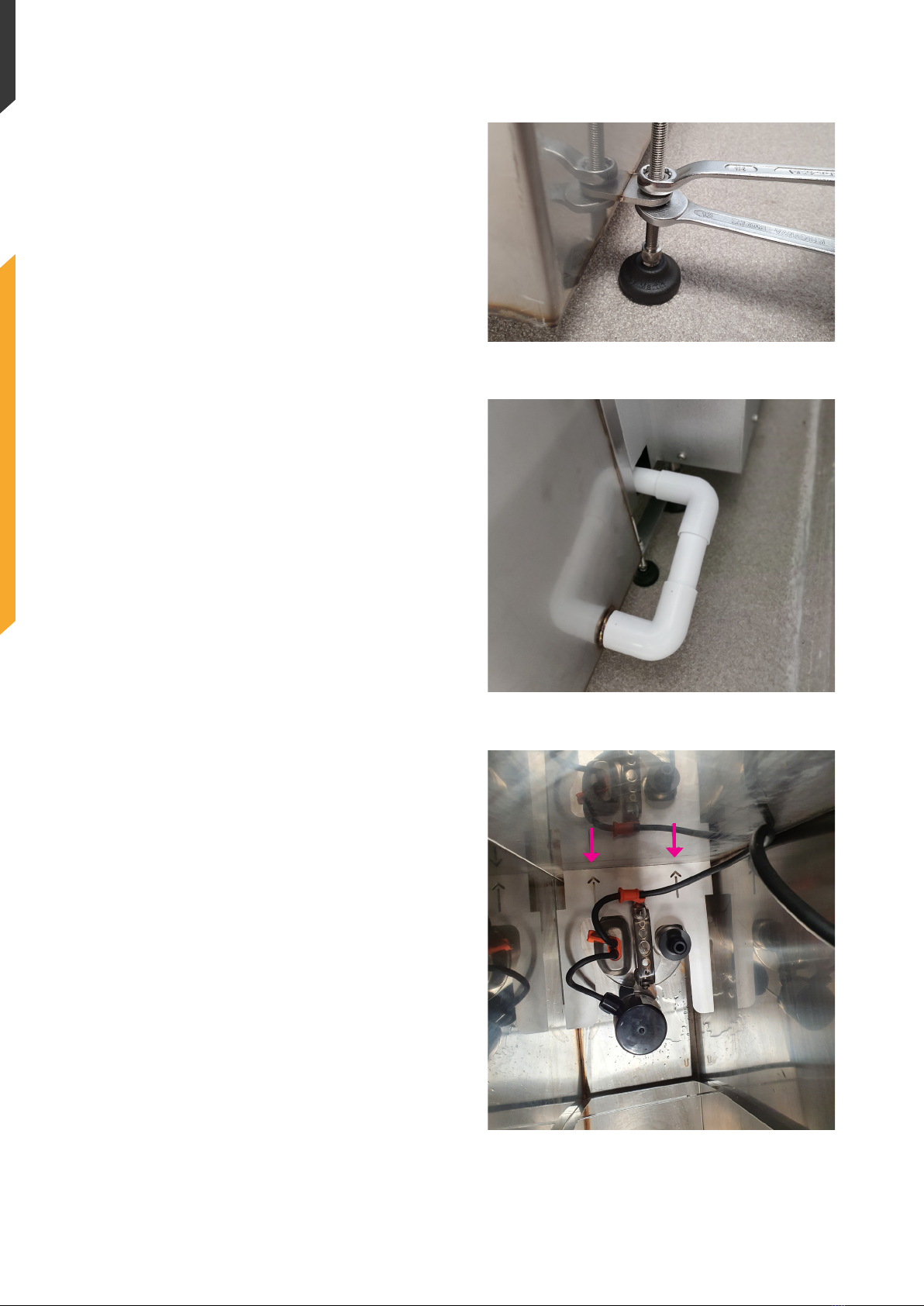
4.3 Tank installation
1. On the right hand side of the Solo Resce®,
loosen the nuts on the levelling feet and
position the tank. Fixate it by tightening the nuts
again (Fig. 10).
2. Make sure the tank is in level by adjusting its
feet (Fig. 11).
Continues on next page –>
Figure 10
Figure 11
10
4 Installation
Figure 12
Figure 13
Figure 14
3. Once it is level, tighten the nuts on the tank feet
(Fig. 12).
4. Connect the included drain pipe connections
between the Solo Rescue® drain outlet and the
tank inlet (Fig. 13).
5. Place the provided submersible pump in the
tank and make sure the arrows on the anti-
rotation plate points to the front of the tank
(Fig. 14)
Continues on next page –>
11
4 Installation
Figure 15 Figure 16
Figure 17
Figure 18
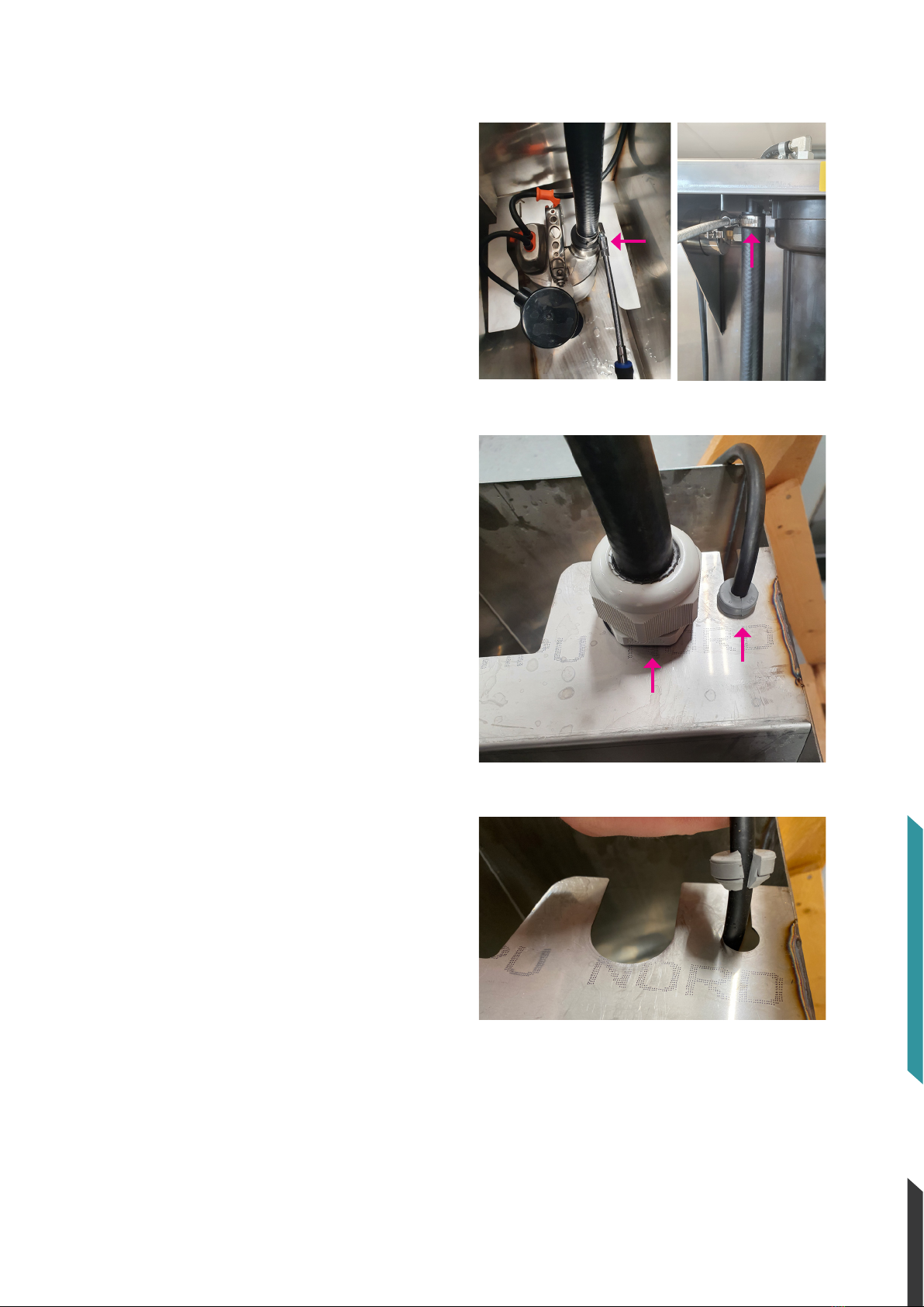
6. Cut the provided hose to suitable length from
pump outlet to filter inlet at filter housing #1 (Fig.
15 & 16).
7. Connect the hose to the pump outlet and
secure it with one of the provided hose clamps
(Fig. 15).
8. Pull the hose through the cable gland and
secure it to the tank using the locknut (Fig. 17).
9. Secure the power cable with the rubber
grommet (Fig. 17 & 18)
Continues on next page –>
Inhaltsverzeichnis


