samlexsolar SCC-30AB Bedienungsanleitung

30 Amp
Solar Charge
Controller
SCC-30AB
Owner's
Manual
Please read this
manual before
operating your
charge controller.

2
1. Safety Instructions .............................................................................................. 3
2. General Description of PV / Solar System .......................................................... 5
3. General information - Batteries ...................................................................... 15
4. Introduction and Features ............................................................................... 24
5. Construction, Layout and Controls .................................................................. 30
6. Installation and Operation .............................................................................. 34
7. Troubleshooting ............................................................................................... 41
8. Specications .................................................................................................... 43
9. Warranty ........................................................................................................... 44
INDEX

3
1
SAFETY INSTRUCTIONS
Please read these instructions before installing or operating the Charge Controller to
prevent personal injury or damage to the Charge Controller.
General
Installation and wiring compliance
• Installation and wiring must comply with the local and National Electrical
Codes and must be done by a certied electrician.
Preventing electrical shock
• The negative system conductor should be properly grounded. Grounding
should comply with local codes.
• Disassembly / repair should be carried out by qualied personnel only.
• Disconnect all input and output side connections before working on any
circuits associated with the Charge Controller. Turning the on/off control on
the Charge Controller to off position may not entirely remove dangerous
voltages.
• Be careful when touching bare terminals of capacitors. The capacitors may
retain high lethal voltages even after the power has been removed. Discharge
the capacitors before working on the circuits.
Installation environment
• The Charge Controller should be installed indoor only in a well ventilated,
cool, dry environment
• Do not expose to moisture, rain, snow or liquids of any type.
Preventing re and explosion hazards
• Working with the Charge Controller may produce arcs or sparks. Thus, the
Charge Controller should not be used in areas where there are inammable
materials or gases requiring ignition protected equip ment. These areas may
include spaces containing gasoline powered machinery, fuel tanks, battery
compartments.
Precautions when working with batteries
• Batteries contain very corrosive diluted sulphuric acid as electrolyte.
Precautions should be taken to prevent contact with skin, eyes or clothing.
• Batteries generate hydrogen and oxygen during charging resulting in
evolution of explosive gas mixture. Care should be taken to ventilate the
battery area and follow the battery manufacturer’s recommendations.
• Never smoke or allow a spark or ame near the batteries.

4
1
SAFETY INSTRUCTIONS
• Use caution to reduce the risk of dropping a metal tool on the battery. It could
spark or short circuit the battery or other electrical parts and could cause an
explosion.
• Remove metal items like rings, bracelets and watches when working with
batteries. The batteries can produce a short circuit current high enough to weld a
ring or the like to metal and thus cause a severe burn.
• If you need to remove a battery, always remove the ground terminal from the
battery rst. Make sure that all the accessories are off so that you do not cause a
spark.
Charge Controller related
• It is to be ensured that the input voltage fed to the Charge Controller does not
exceed 50 VDC to prevent permanent damage to the Charge Controller. Ensure
that the maximum Open Circuit Voltage Voc of the 12 V nominal Solar Panel /
the Solar Array is less than 50 V. If two 12 V nominal Solar Panels are being used
in series to make a 24 V nominal Solar Array, make sure that the maximum Open
Circuit Voltage Voc of each of the 12 V Panels is less than 25 V.
• Do not exceed the maximum current rating of 30 A. The Short Circuit Current of
the Solar Array should be less than 30 A
• Do not exceed a battery voltage of 24V (nominal) . Do not use a battery less than
12V.
• Charge only 12, or 24 volt Lead-Acid batteries when using the standard battery
charging programs or Ni-Cd batteries when DIP Switch number 2~4 is in the ON
position.
• DO NOT short circuit the PV array or load while connected to the controller. This
will damage the controller.
• The controller should be protected from direct sunlight. Ensure adequate space
for air ow around the controller’s face plate.
• Do not install in a sealed compartment with batteries.
• Never allow the solar array to be connected to the controller with the battery
disconnected. This can be a dangerous condition with high open-circuit solar
voltage present at the terminals.
• Use only copper wire with minimum 75°C insulation rating and between 10 AWG
(5.2 mm2) and 14 AWG (2.1 mm2) gauge.
• The Negative system conductor should be properly grounded. Grounding should
comply with local codes.
5
2
GENERAL DESCRIPTION OF PV / SOLAR SYSTEM
What is Photovoltaic (PV)?
The word ‘photo-voltaic’ is derived from two different words; the word ‘photos’,
from the Greek, meaning light and the word ‘voltaic’ developed from the name of the
Italian scientist, Volta, who studied electricity. This explains what a PV system does: it
converts light energy from the sun into electrical energy.
What is in a Photovoltaic (PV) system?
Non Grid-tied PV / Solar System
PV/Solar Panel (Module) or Array
Charge Controller
Battery
DC-AC Power Inverter
To AC
Loads
Solar Array
Charge
Controller/Protection
DC-AC Power Inverter
To AC
Loads
Power to
and from grid
Two-way Metering
Fig. 2.1. Non Grid-tied PV System–Block Diagram
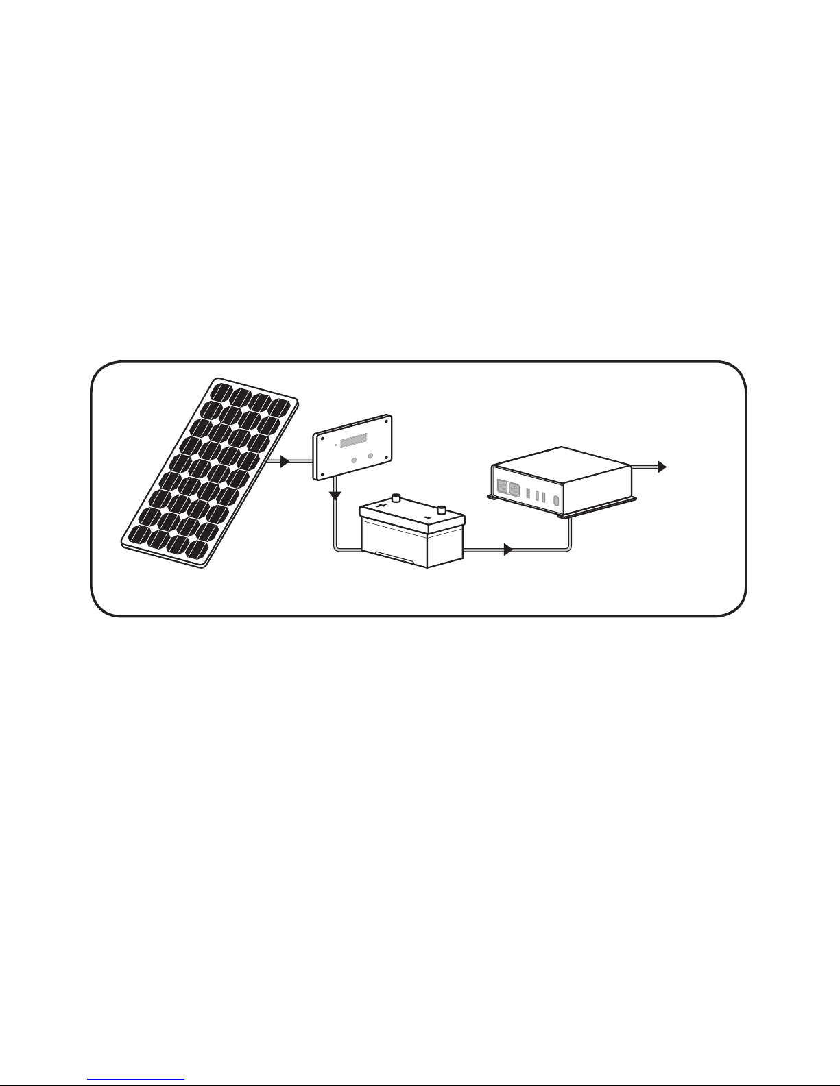
Fig. 2.1 shows a Block Diagram of a typical non-grid tied Photovoltaic (PV) System
with its main components. It consists of a PV / Solar Panel (Module), Charge Controller,
Batteries and Power Inverter. The PV / Solar Panel (Module) or Array converts the
solar light energy into DC electrical energy. The Charge Controller conditions the DC
electrical voltage and current produced by the PV / Solar Panel (Module) or Array to
charge a battery. The battery stores the DC electrical energy so that it can be used
when there is no solar energy available (night time, cloudy days etc). DC loads can be
powered directly from the PV / Solar Panel (Module) / Battery. The inverter converts
the DC power produced by the PV / Solar Panel (Module) / stored in the battery into
AC power to enable powering of AC loads.

6
2
GENERAL DESCRIPTION OF PV / SOLAR SYSTEM
Grid-tied PV / Solar System
Fig. 2.2 shows a Block Diagram of a typical Grid-tied PV / Solar System. In this system,
the Solar Panels (Modules) / Arrays directly feed to an inverter and the inverter is
connected to an Electricity Transmission and Distribution System (referred to as the
Electricity Grid) such that the system can draw on the Grid’s reserve capacity in times
of need, and feed electricity back into the Grid during times of excess production.
PV/Solar Panel (Module) or Array
Charge Controller
Battery
DC-AC Power Inverter
To AC
Loads
Solar Array
Charge
Controller/Protection
DC-AC Power Inverter
To AC
Loads
Power to
and from grid
Two-way Metering
Fig. 2.2 Grid-tied PV / Solar System – Block Diagram
In order to safely transmit electricity to your loads and to comply with your power
provider’s grid-connection requirements, you may need the following additional
items:
• Power conditioning equipment
• Safety equipment
• Meters and instrumentation.

7
2
GENERAL DESCRIPTION OF PV / SOLAR SYSTEM
PV / Solar Cell
12cm
Fig. 2.3. PV / Solar Cell
The basic element of a PV System is the photovoltaic (PV) cell, also called a Solar Cell.
An example of a PV / Solar Cell made of Mono-crystalline Silicon is shown in Fig. 2.3.
This single PV / Solar Cell is like a square but with its four corners missing (it is made
this way!).
Theory of Operation of PV / Solar Cell
Sunlight (photons)
External circuit
Encapsulate seal
Top electrical contact
P-Type material
(Boran-doped Silicon)
N-Type material
(Phosphorous-doped Silicon)
P/N junction
Base contact
Figure 2.4: Construction and Working of PV / Solar Cell
A PV / Solar Cell is a semiconductor device that can convert solar energy into DC
electricity through the “Photovoltaic Effect” (Conversion of solar light energy into
electrical energy). When light shines on a PV / Solar Cell, it may be reected, absorbed,
or passes right through. But only the absorbed light generates electricity.

8
2
GENERAL DESCRIPTION OF PV / SOLAR SYSTEM
When light enters the PV / Solar Cell, some of the “Photons” (packets of electro-
magnetic wave energy) from the light energy are absorbed by the semiconductor
atoms. The energy of the absorbed light is transferred to the negatively charged
electrons in the atoms of the solar cell. With their newfound energy, these electrons
escape from their normal positions in the atoms of the semiconductor photovoltaic
material and become part of the electrical ow, or current, in an electrical circuit. A
special electrical property of the PV / Solar Cell – a built-in electric eld – provides the
force, or voltage, needed to drive the current through an external load, such as a
light bulb.
To induce the built-in electric eld within a PV / Solar Cell, two layers of somewhat
differing semiconductor materials are placed in contact with one another (See Fig. 2.4).
One layer is an N-type semiconductor (e.g. Phosphorus doped Silicon) with an abundance
of “Electrons”, which have a Negative electrical charge. The other layer is a P-type
semiconductor (e.g. Boron doped Silicon) with an abundance of” Holes”, which have a
Positive electrical charge.
Although both materials are electrically neutral, N-type silicon has excess Electrons and
P-type silicon has excess Holes. Sandwiching these together creates a P-N Junction at their
interface, thereby creating an electric eld.
When N-type and P-type silicon come into contact, excess electrons move from the
N-type side to the P-type side. The result is a buildup of Positive charge along the
N-type side of the interface and a buildup of Negative charge along the P-type side.
Because of the ow of electrons and holes, the two semiconductors behave like a battery,
creating an electric eld at the surface where they meet – the P/N Junction. The electrical
eld causes the electrons to move from the semiconductor toward the Negative surface,
where they become available to the electrical circuit. At the same time, the Holes move in
the opposite direction, toward the positive surface, where they await incoming electrons.
The electrical current is fed to the external load through the top electrical contact surface
(normally in the form of a grid) and the bottom base contact.
The Open Circuit Voltage Voc of a PV /Solar Cell is just under 0.6 V
Factors Affecting Voltage and Current Output of the PV / Solar Cell
The amount of electric current generated by photon excitation in a PV / Solar Cell at
a given temperature is affected by the incident light in two ways:
• By the intensity of the incident light.
• By the wavelength of the incident rays.

9
2
GENERAL DESCRIPTION OF PV / SOLAR SYSTEM
The materials used in PV / Solar Cells have different spectral responses to incident
light, and exhibit a varying sensitivity with respect to the absorption of photons at
given wavelengths.Each semiconductor material will have an incident radiation
threshold frequency, below which no electrons will be subjected to the photovoltaic
effect. Above the threshold frequency, the kinetic energy of the emitted
photoelectron varies according to the wavelength of the incident radiation, but
has no relation to the light intensity. Increasing light intensity will proportionally
increase the rate of photoelectron emission in the photovoltaic material. In actual
applications, the light absorbed by a PV cell will be a combination of direct solar
radiation, as well as diffused light bounced off of surrounding surfaces. PV / Solar
Cells are usually coated with anti-reective material so that they absorb the maximum
amount of radiation possible.
The output current of the PV / Solar Panel (Module) can increase due to what is
known as the “Edge of the Cloud Effect”. As the sun moves into a hole between the
clouds, your solar panels will see full direct sunlight combined with reected light
from the clouds! They will absorb more energy than they could on a cloudless day!
Thus, a factor of 1.25 times the Short Circuit Current Isc is recommended when sizing
the current capacity of the Charge Controller
The output current of the PV / Solar Cell has a positive Temperature Coefcient – The
output current increases with the rise of temperature. However, it is negligible – less
than 0.1 % / °C of the Short Circuit Current Isc
The output voltage of the PV / Solar Cell has a Negative Temperature Coefcient –
The output voltage increases with decrease in temperature. For example, a Silicon
Cell has a Temperature Coefcient of – 2.3 mV / °C / Cell. Hence, during cold winter
days, the voltage will rise. Hence, as a Thumb Rule, the voltage rating of the Charge
Controller should be sized as 1.25 times the Open Circuit Voltage rating Voc of the PV
/ Solar Panel (Module) to ensure that the Charge Controller is not damaged due to
over-voltage.

10
2
GENERAL DESCRIPTION OF PV / SOLAR SYSTEM
PV Cell Types
PV cells are most commonly made of Silicon, and come in two varieties, crystalline and
thin-lm type, as detailed in Table 2.1
Cell types include Mono-crystalline Silicon, Poly-crystalline Silicon, Amorphous Silicon
(a-Si), Gallium Arsenide (GaAs), Copper Indium Diselenide (CuInSe2, „CIS“), Cadmium
Telluride, or a combination of two materials in a tandem cell.
Bulk type / Wafer-based (Crystalline)
Mono Crystalline Si Poly Crystalline Si Poly Crystalline Band
Pros High efciency High efciency with
respect to price -
Cons Increased manufacturing cost caused by the
supply shortage of silicon -
Thin lm type
Amorphous Si CIGS CdTe Polymer organic
Pros Low price
Low price
Able to automate
all manufacturing
process
Low manufacturing
Can be more efcient
(still in research)
Cons Low efciency Low efciency
Table 2.1 PV Cell Types
PV Module / Panel and PV Array
To increase their utility, a number of individual PV cells are interconnected together
in a sealed, weatherproof package called a Panel (Module). For example, a 12 V Panel
(Module) will have 36 cells connected in series and a 24 V Panel (Module) will have 72
PV Cells connected in series
To achieve the desired voltage and current, Modules are wired in series and parallel
into what is called a PV Array. The exibility of the modular PV system allows
designers to create solar power systems that can meet a wide variety of electrical
needs. Fig. 2.5 shows PV cell, Panel (Module) and Array.
Inhaltsverzeichnis
Andere samlexsolar Controller Handbücher


