SANICA FIJI Bedienungsanleitung

1
FIJI
24 - 28 KW HERMETIC CONVENTIONAL BOILER
INSTALLATION AND USER MANUAL

2
TABLE OF CONTENTS
1-INTRODUCTION ..................................................................................................... 3
2-USER WARNINGS................................................................................................... 3
3-EXCLUSION OF WARRANTY ................................................................................... 4
4-STARTING THE BOILER........................................................................................... 4
5-DAILY USAGE OF THE BOILER ................................................................................ 5
6-FILLING BOILER WITH WATER................................................................................ 6
8-BOILER MAINTENANCE.......................................................................................... 7
9-INSTALLATION INSTRUCTIONS .............................................................................. 8
10-BOILER DIMENSIONS ........................................................................................... 9
11-FLUE CONNECTION.............................................................................................. 9
12-ELECTRICAL CONNECTION................................................................................. 12
13-CIRCUIT SCHEME AND ROOM THERMOSTAT.................................................... 12
14-MALFUNCTION CODES ...................................................................................... 13
15-TECHNICAL FEATURES ....................................................................................... 14

3
1-INTRODUCTION
First of all, thank you for choosing SANICA brand. SANICA conventional combi
boilers are designed for efficient, safe and comfortable central heating and domestic
hot water needs.
SANICA FIJI 24kW - 28kW hermetic conventional combi boilers are designed and
produced to serve according to the need for hot tap water and heating, using natural
gas fuel. The devices are suitable for use with natural gas fuel. There are necessary
information for safe and efficient use of combi boilers in the Installation and User
Manual. In this booklet; technical information, installation and connection
information of the device, information about maintenance and possible
malfunctions and explanations are included. Please do not use your device before
reading this booklet and keep it in case it is necessary.
2- WARRANTY AND SERVİC
a. The assembly and connections of the boiler must be done in accordance with the
condi-tions specified by TSE and authorized gas organizations, as specified in the
manual.
b. Make sure that the flue connection is not opened to a closed environment and
that it is not connected with any device other than the special chimney used for
connecting more than one device, and that the chimney head is not blocked.
c. It should be ensured that the boiler will be used with a suitable gas.
d. It should be ensured that the connected piping and pipes are cleaned before
installation. Otherwise, malfunctions caused by dirt and particles in the
installation are out of the scope of warranty.
e. The first start-up of the combi must be done by the authorized service. Make sure
that the electricity, water and gas connections of the device are made completely.
f. The outer surface of the device should be cleaned with a damp cloth without using
any chemicals or detergents.
g. In order to use the device efficiently for many years, have an annual maintenance
done by the authorized service regularly every year.
CAUTION: This appliance is not intended for use by persons (including children} with
reduced physical, sensory or mental capabilities, or lack of experience and knowledge,
unless they have been given supervision or instruction concerning use of the appliance
by a person responsible for their safety. Children must be supervised to ensure that they
do not play with the appliance. Cleaning and user maintenance should not be made by
children without supervision.

4
CAUTION: This device; is not suitable for use by persons (including children) with reduced
physical, sensory and mental capabilities, or ignorant and inexperienced persons, without
being informed and supervised by responsible persons. Make sure that children do not play
with the device.
3-EXCLUSION OF WARRANTY
The warranty given by SANICA does not cover the malfunctions arising from the
abnormal use of the device and the following situations:
a. Malfunctions in devices not first started by SANICA authorized services.
b. Malfunctions arising from the assembly and use of the device contrary to the
conditions stated in the user manual.
c. Malfunctions caused by incorrect type selection,
d. Damages and failures caused by intervention to the device other than the
authorized service.
e. Physical damages occurring after the delivery of the device.
f. Damage caused by fire and lightning.
g. Malfunctions caused by low or high voltage or not grounding.
h. Malfunctions arising from not having the described periodic maintenance works
deliv-ered by our authorized services on time.
I. Malfunctions caused by other accessories and products used with the
device. j. Damages caused by frost.
k. Falsification of the registration label and warranty certificate.
l. Malfunctions caused by operation of the device outside the water conditions
specified in the user manual.
The above mentioned malfunctions and damages are out of warranty and are
handled for a fee.
4-STARTING THE BOILER
Make sure that the electricity, water and gas connections of the device have
been made and the necessary supply energies are turned on. a. Open the energy
connection.
b. Turn the gas valve to open.
c. Turn the switch to the operating position by turning the Summer or Winter mode
accord-ing to your wishes. The open button is also the Summer / Winter position
button. (Figure.1) WARNING: In summer mode, the device will not be activated
as long as the domestic water is not turned on.

5
d. Adjust the temperature adjustment knobs to the desired temperature and ensure
the reflection of the device.
WARNING: When the device is started for the first time, until the air in the gas pipe
is expelled, the device may fail several times with ignition errors. In this case turn
the on / off switch to off position and wait for 3 seconds to turn your device on
again. (Figure 1)
5-DAILY USAGE OF THE BOILER
Summer / Winter usage mode selection; When there is no need to use the heater
heating feature of the device, the device can be switched to summer mode to
operate only the domestic water heating. To make this setting, you need to the On /
Off switch to position.
WARNING: When the device is off, the blockage safety of the pump is a active , the
frost protection is not active.
a - When the device is used in summer mode and domestic water circuit, there is (
) mark on the screen. For domestic water adjustment, adjust the ( ) button in
the direction of the thickness of the lines and adjust the desired temperature by
looking on the screen. Pump blockage protection and frost protection are active in
the summer position.
b - When the device is switched to winter mode, there are ( ) and ( )signs on the
screen. For this choice; The ( )mode setting button should be between the min
and max texts.
c - For the adjustment of the radiator temperature, adjust the desired temperature
ac-cording to the temperature value on the screen by turning the ( ) button in the
direction from min to max.
d - For domestic water adjustment, adjust the ( )button in the direction of the
thickness of the lines and adjust the desired temperature by looking on the screen.
Domestic Water
adjustment knob
Heater
Button
Figure.1
On/Off and Summer/
Winter position
button

6
e - Pump blockage protection and frost protection are active in the winter position.
WARNING: When the device starts to operate (when the burner ignites) sign is
displayed on the screen during the burning period.
6-FILLING BOILER WITH WATER
Water supply is made from the filling valve shown in Figure 3 located at the bottom of
the device. While the device is cold, the water level should be filled in a range of 1 -
1.5 bars on the manometer located on the front of the device (Figure 2). When the
water pressure of the device drops to a critical level, the device automatically stops.
WARNING: In order to fill the device with water, it must be switched to heating
(winter) mode. When the device is in domestic water (summer) mode, water
filling operation cannot be done.
Figurel 3
Figure 2
Manometre
Filling
Valve

7
7-TURNING OFF THE BOILER
In order to turn off device you need to turn turn the button to the off position.
When the device is turned off, the pump blocking safety is active, the frost
protection is not active and there is an electric current in the device. In order to
cut off the electric current, electricity must be cut off from the main fuse.
WARNING: The electrical connection and gas connection of the device must not be
disconnected for the frost protection to be active. The conditions in clause.
4 should be observed. When the water in the device falls below 5 degrees, it is
activated and heats up to 30 degrees.
8- BOILER MAINTENANCE
In order to use your device smoothly and efficiently for a long time, have it annually
examined by the authorized service at the beginning of the season.
Never clean the outer surface of your device with detergent or chemicals.
Check your installment before connecting the device and make sure that there
are no foreign particles in the installation.
The useful life of the combi boilers determined and announced by the Ministry of
Science, Industry and Technology is 15 years. Within this period, the manufacturers
undertake to keep the spare parts of the device as per the relevant law.

8
9-INSTALLATION INSTRUCTIONS
Boiler packaging content; boiler support styrofoam,
assembly hanger equipment, user manual,
warranty certificate and service booklet.
The places where the device will be mounted
should be selected by checking the conditions
determined by TSE and authorized gas
organizations. Mounting hanging equipment must
be securely mounted on the wall to carry the
weight of the boiler. The device must be mounted
on the hanging equipment to be level.
It is recommended to leave a gap of 50 cm from the
top, 15 cm from the sides and 40 cm from the
bottom where the boiler will be mounted. For
water connections, a filter and a ball valve must be
installed at the inlets of the combi. (Figure 5) The
mains inlet should not be over the 8 bar pressure
limit. In cases with higher network pressure, a pressure reducer must be installed.
The suitability of the gas installation and the device should be checked.
Warning: The safety valve connection must be
given to the installation drainage line.
Şekil 5
Safety
valve
Radiator out
going
connection
Domestic hot
water outler
connection
Gas
connection
Domestic hot
water inlet
Connection
Heater return
connecti on (inlet)
Figure 4

9
10. BOILER DIMENSIONS
Combi boiler dimensions are as in Figure 6.
Figure 6 a Figure 6 b
(Side) (Front)
11-FLUE CONNECTION
The accessories provided by the manufacturer must be used in the device. Attention
should be paid to the condition of the flue connection in the selection of the place
where the device will be mounted. For the flue connection, the conditions
determined by TSE and authorized gas organizations must be complied with.
Chimney connection cannot be applied to the following places;
a. In the stairwells of the buildings.
b. Building corridors.
c. To the wells
D. On the chimney wall.
e. To the balconies.
f. elevator shafts.
The following points should be taken into consideration in the flue connection:
a. In cases where the chimney is removed from the roof, care should be taken to
keep the chimney inlet 1.5 m from the top of the roof and coatings.
b. It should be at least 0.3 high from the ground and in a wireframe where there is a
risk of impact.
c. When the chimney is taken out of the wall, it must be at least 18 mm outside the
wall.

10
d. Horizontally connected flue connections should be mounted downward with a
slope of 1%.
e. If the device is installed in attics, the chimney should be at least 40 cm above the
roof. In these cases, it should be insulated with fire resistant material.
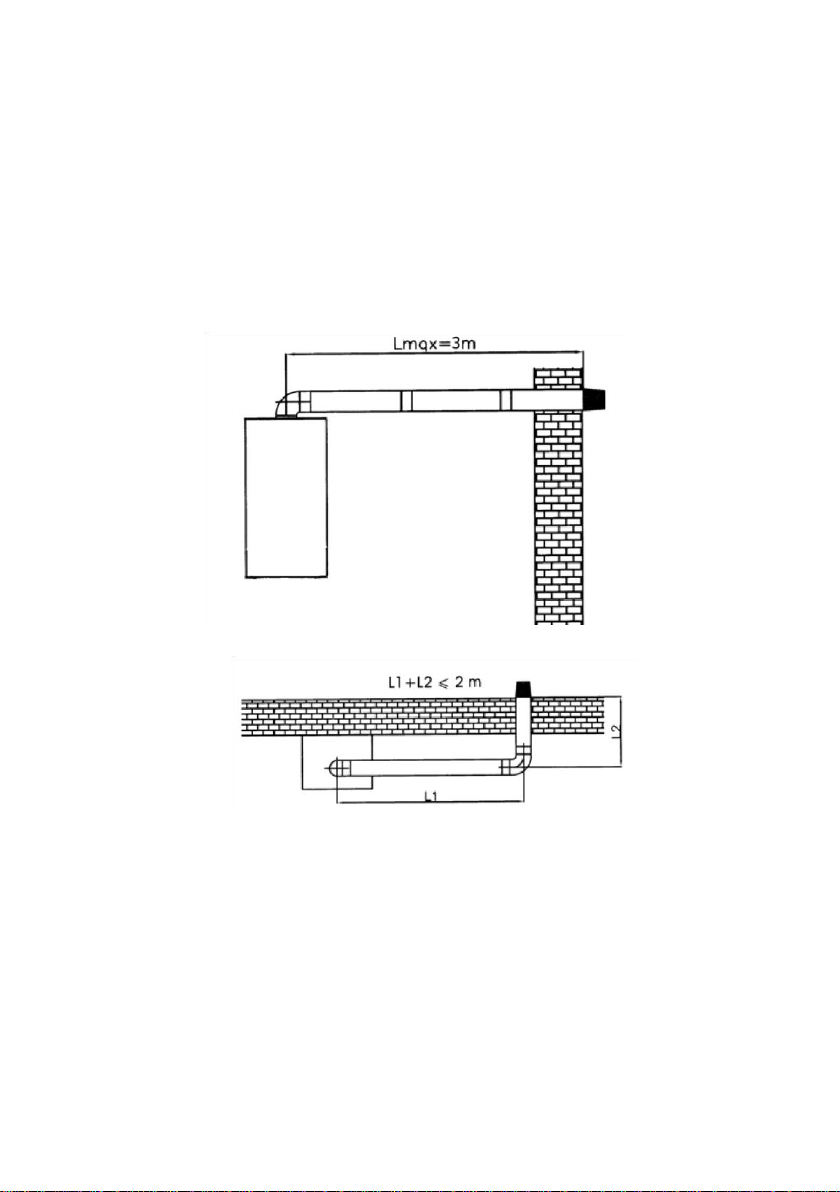
f. The maximum chimney length of the device is 3 m. Maximum chimney length is
short-ened by 1 m for each 90 ° elbow and 0.5 m for each 45 ° pole.
g. In vertical chimney applications, roof tightness must be fully ensured. Possible
malfunc-tions that may occur in the device in cases where the sealing is not
ensured are excluded from the scope of warranty.
Şekil 7
Şekil 8
3
m
2
m
Dieses Handbuch passt für folgende Modelle
2
Inhaltsverzeichnis
Beliebte Kessel Handbücher anderer Marken

Vaillant
Vaillant uniSTOR VIH SW GB 500 BES Bedienungsanleitung

Radijator
Radijator BIO max 23.1 Bedienungsanleitung

Brunner
Brunner BSV 20 Bedienungsanleitung

Buderus
Buderus Logamax GB062-24 KDE H V2 Bedienungsanleitung

Potterton
Potterton 50e Datenblatt

UTICA BOILERS
UTICA BOILERS TriFire Bedienungsanleitung