SBM SX Series Bedienungsanleitung

Manufacturer : Agent :
SBM
3 cottages de la Norge
21490 CLENAY - FRANCE
1
GAS INFRARED HEATERS
SX INSTALLER INSTRUCTIONS
Nr 05000048/11
1.
PRODUCT SPECIFICATION
Pages
2 to 4
1.1 Technical specifications ......................................................................... 2 to 3
1.2 SX heater dimensions ............................................................................ 4
2.
INSTALLATION
Pages
5 to 14
2.1 Rules and regulations ............................................................................ 5
2.2 Diagram of a standard installation .......................................................... 5
2.3 Unpacking and checking of equipment .................................................. 6
2.4 Fixing of heaters .................................................................................... 6 to 8
2.5 Minimum safety distances ...................................................................... 9
2.6 Inclination of heaters .............................................................................. 9 to 10
2.7 Gas connection ...................................................................................... 11 to 12
2.8 Electrical connections ............................................................................ 12 to 13
2.9 Start-up .................................................................................................. 14 to 15
3.
RECEIPT OF INSTALL
ATION
Page
1
6
4.
MAINTENANCE
Page
1
7
5.
REPAIRS
Pages
1
8
to 2
1
6.
CHANGING THE GAS USED
Page
2
1

2
1. PRODUCT SPECIFICATION
1.1 Technical specifications :
GAS : G20 (Natural gas) - Category : I2Esi
MODEL
B6
SX
B8
SX
B10
SX
B12
SX
B16
SX
B20
SX
B20
2SX
B24
SX
B24
2SX
B32
SX
B32
2SX
B4
8
2SX
B64
2SX
Weight (kg) 2.5 2.9 3.1 3.4 4.1 5.0 5.0 5.5 5.5 6.7 6.7 9.4 12.2
Net calorific value
Qn (kW) Hi 2.50 3.30 3.80 5.10 6.75 7.60 7.60 10.20 10.20 13.50 13.50 20.25 27.00
GAS
Inlet pressure 20 mbar
Injection pressure (mbar) 13.0 11.0 12.0 15.0 16.7 12.0 12.0 15.0 15.0 16.7 16.7 (See B)
16.7
Gas consumption (m3/h) 0.265 0.350 0.400 0.540 0.715 0.805 0.805 1.080 1.080 1.430 1.430 2.145 2.860
Ø prim. Inject. (1/100 mm) 170 180 195 240 320 260 2x195 380 2x240 - 2x320 (See A)
-
Ø sec. Inject. (1/100 mm) 135 165 170 180 195 2x170 2x170 2x180 2x180 2x195 2x195 (See A)
4x195
Gas input connection
Fitting G1/2" cylindrical (ISO 228-1) or Tapered fitting R1/2" conical (ISO 7-1)
ELECTRICITY
Power supply 230V (+10% -15%) - 50Hz Neutral mandatory
Consumption 0.1A 2x0.1A
0.1A 2x0.1A
0.1A 2x0.1A
Individual fuse 0.25A 2x0.25A
0.25A 2x0.25A
0.25A 2x0.25A
Ignition cycle length 45 seconds
VENTILATION
Combustion air (m3/h) 2.60 3.40 3.90 5.30 7.00 7.90 7.90 10.50 10.50 13.90 13.90 21.00 27.80
Req. air change (m3/h) 25 33 38 51 67.5 76 76 102 102 135 135 202.5 270
GAZ : G31 (Propane) - Category : I3P
MODEL
B6
SX
B8
SX
B10
SX
B12
SX
B16
SX
B20
SX
B20
2SX
B24
SX
B24
2SX
B32
SX
B32
2SX
B4
8
2SX
B64
2SX
Weight (kg) 2.5 2.9 3.1 3.4 4.1 5.0 5.0 5.5 5.5 6.7 6.7 9.4 12.2
Net calorific value
Qn (kW) Hi 2.50 3.30 3.80 5.10 6.75 7.60 7.60 10.20 10.20 13.50 13.50 20.25 27.00
GAS
Inlet pressure 37 mbar
Injection pressure (mbar) 34.0 21.0 21.0 28.0 37.0 21.0 21.0 27.5 28.0 34.0 37.0 (See B)
34.0
Gas consumption (kg/h) 0.195 0.260 0.300 0.400 0.530 0.595 0.595 0.800 0.800 1.055 1.055 1.590 2.110
Ø prim. Inject. (1/100 mm) 155 140 130 180 - 185 2x130 240 2x180 370 - (See A)
2x370
Ø sec. Inject. (1/100 mm) 82 105 110 125 135 2x110 2x110 2x125 2x125 2x135 2x135 (See A)
4x135
Gas input connection
Fitting G1/2" cylindrical (ISO 228-1) or Tapered fitting R1/2" conical (ISO 7-1)
ELECTRICITY
Power supply 230V (+10% -15%) - 50Hz Neutral mandatory
Consumption 0.1A 2x0.1A
0.1A 2x0.1A
0.1A 2x0.1A
Individual fuse 0.25A 2x0.25A
0.25A 2x0.25A
0.25A 2x0.25A
Ignition cycle length 45 seconds
VENTILATION
Combustion air (m3/h) 2.30 3.10 3.60 4.80 6.30 7.10 7.10 9.60 9.60 12.60 12.60 18.90 25.20
Req. air change (m3/h) 25 33 38 51 67.5 76 76 102 102 135 135 202.5 270

3
GAZ : G31 (Propane) - Category : I3P
MODEL
B6
SX
B8
SX
B10
SX
B12
SX
B16
SX
B20
SX
B20
2SX
B24
SX
B24
2SX
B32
SX
B32
2SX
B4
8
2SX
B64
2SX
Weight (kg) 2.5 2.9 3.1 3.4 4.1 5.0 5.0 5.5 5.5 6.7 6.7 9.4 12.2
Net calorific value
Qn (kW) Hi 2.50 3.30 3.80 5.10 6.75 7.60 7.60 10.20 10.20 13.50 13.50 20.25 27.00
GAS
Inlet pressure 30 mbar
Injection pressure (mbar) 30.0 21.0 21.0 28.0 30.0 21.0 21.0 28.0 28.0 28.0 30.0 (See B)
28.0
Gas consumption (kg/h) 0.195 0.260 0.300 0.400 0.530 0.595 0.595 0.800 0.800 1.055 1.055 1.590 2.110
Ø prim. Inject. (1/100 mm) - 130 145 220 - 210 2x145 260 2x220 - - (See A)
-
Ø sec. Inject. (1/100 mm) 82 105 110 125 137 2x110 2x110 2x125 2x125 2x137 2x137 (See A)
4x137
Gas input connection
Fitting G1/2" cylindrical (ISO 228-1) or Tapered fitting R1/2" conical (ISO 7-1)
ELECTRICITY
Power supply 230V (+10% -15%) - 50Hz Neutral mandatory
Consumption 0.1A 2x0.1A
0.1A 2x0.1A
0.1A 2x0.1A
Individual fuse 0.25A 2x0.25A
0.25A 2x0.25A
0.25A 2x0.25A
Ignition cycle length 45 seconds
VENTILATION
Combustion air (m3/h)
2.30 3.10 3.60 4.80 6.30 7.10 7.10 9.60 9.60 12.60 12.60 18.90 25.20
Req. air change (m3/h) 25 33 38 51 67.5 76 76 102 102 135 135 202.5 270
G20 prim : -
sec : 2 x 195
prim : 320
sec : 195
G31-37 prim : 370
sec : 2 x 135
prim : -
sec : 135
G31-30 prim : -
sec : 2 x 137
prim : -
sec : 137
G20
16,7 mbar 16,7 mbar
G31
-
37
34,0 mbar 37,0 mbar
G31
-
30
28,0 mbar 30,0 mbar
B48-2SX
A
B

4
1.2 SX heater dimensions :
B6, B8, B10, B12 and B16 SX
70
202
147 172
26
A
B
C
MODEL B6-SX B8-SX B10-SX
B12-SX
B16-SX
A (mm) 186 218 243 281 299
B (mm) 222 285 334 411 536
C (mm) 318 382 431 508 632
B20, B20-2, B24, B24-2, B32 and B32-2SX
70
332
147 172
26
A
B
C
MODEL B20-SX
B20-2SX
B24-SX
B24-2SX
B32-SX
B32-2SX
A (mm) 243 243 281 281 299 299
B (mm) 334 334 411 411 536 536
C (mm) 431 431 508 508 632 632
B48-2 SX
B64-2 SX

5
2. INSTALLATION
2.1 Regulations
THESE HEATERS MUST BE INSTALLED IN ACCORDANCE WITH APPLICABLE
REGULATIONS AND IN WELL VENTILATED PREMISES.
The ideal level of ventilation for the premises is 10 m3/h per kW of heating installed.
2.2 Diagram of a standard installation.
Individual valve
Regulator
Electrical
junction box
Solenoid valve
Electrical cable
(3-conductor insulated
with ground)
SBM infrared heater
Prewired plug
Sensor
Control unit
RCD (Residual Current Device)
Gas filter
Main valve
230V - 50Hz
Gas supply

6
2.3 Unpacking and checking of equipment
Check the type and quantities of equipment against your order.
Check that packing and equipment are intact.
If this is not the case, register a complaint to this effect with the carrier.
Check gas type and pressure to be used on heaters.
2.4 Fixing of heaters
Minimum recommended safety heights :
MODEL MIN HEIGHT (m)
B6-SX 3.00
B8-SX 3.10
B10-SX 3.20
B12-SX 3.40
B16-SX 3.60
B20-SX / B20-2SX 3.80
B24-SX / B24-2SX 4.10
B32-SX / B32-2SX 4.50
B48-2SX 5.00
B64-2SX 5.50
MINIMUM COMFORT HEIGHTS : refer to the specific SBM study for each project.
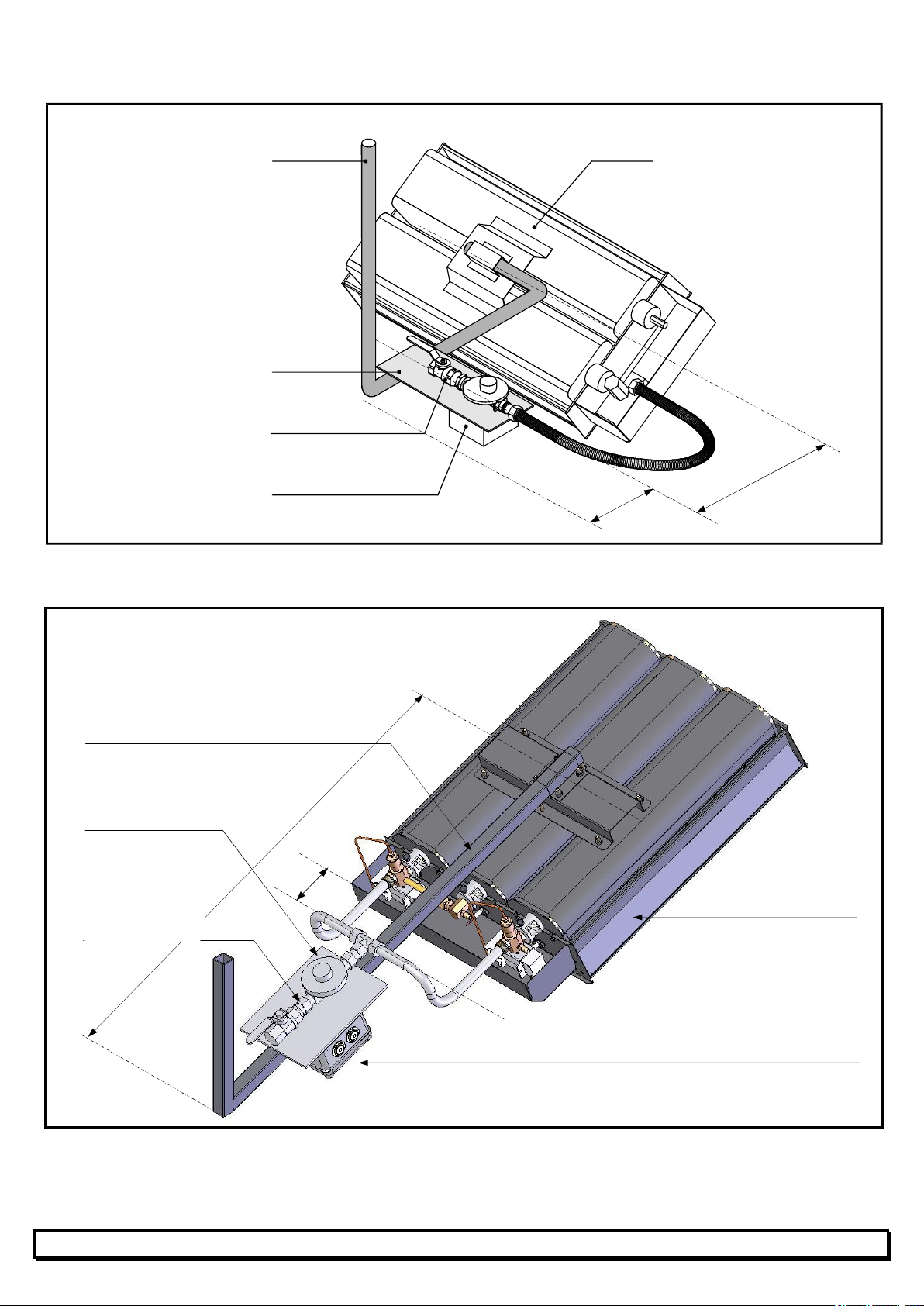
Examples of fixtures to be supplied by the installer :
FOR TYPE B6, B8, B10, B12 and B16 SX HEATERS
Steel tube 3/4"
(not supply by SBM)
Anchoring plate
(not supply by SBM)
Fixed regulator + valve
(supplied by SBM)
RP3
(supplied by SBM)
SBM infrared heater
100
300
Dimensions in mm.
7
FOR TYPE B20, B20-2, B24, B24-2, B32 and B32-2SX HEATERS
FOR TYPE B48-2SX HEATERS
Steel tube 3/4"
(not supply by SBM)
Anchoring plate
(not supply by SBM)
Fixed regulator + valve
(supplied by SBM)
RP3 or RP32
(supplied by SBM)
SBM infrared heater
Steel tube 25x25 mm
(not supply by SBM)
Anchoring plate
(not supply by SBM)
Fixed governor
+ valve
(supplied by SBM)
SBM infrared heater
RP3 or RP32
(supplied by SBM)
Dimensions in mm.
900
100 min.
100
400

8
FOR TYPE B64-2SX HEATERS
Steel tube 25x25 mm
(not supply by SBM)
Anchoring plate
(not supply by SBM)
Fixed regulator + valve
(supplied by SBM)
RP3 or RP32
(supplied by SBM)
SBM infrared heater
100 min.
900
Dimensions in mm.

9
2.5 Minimum safety clearances (Inflammable materials : max = 70°C)
Where safety clearances cannot be respected, heat-protection must be provided above heater.
2.6 Inclination of heaters
In all cases, slope "P" or inclination "I" must be at least 10°.
Always install the automatic ignition block (BA block) in low position.
Lateral inclination "I".
Longitudinal inclination "P".
1 m
min.
0,6 m
min. (*)
2 m
min.
(*) For minimum 20° inclination
1 m
Min.
HEATED
AREA
HEATED AREA
BA BLOCK
IN LOW POSITION
BA BLOCK
IN LOW POSITION
P = 0°
I = 10 to 35°
I = 0°
P = 10 to 35°
HORIZONTAL
HORIZONTAL

10
For B48-2SX
For B64-2SX
For B20-2SX, B24-2SX and B32-2SX with lateral inclination.
ALWAYS LIGHT THE TOP BURNER FIRST.
NO
YES
50%
OPERATION
100%
OPERATION
NO
100%
OPERATION
66%
OPERATION
YES
Andere Handbücher für SX Series
1
Dieses Handbuch passt für folgende Modelle
15
Inhaltsverzeichnis
Andere SBM Heizung Handbücher


Beliebte Heizung Handbücher anderer Marken


Empire Heating Systems
Empire Heating Systems WCC65 Bedienungsanleitung

Wetekom
Wetekom 92 86 43 Bedienungsanleitung

Desa
Desa SPC170-F Bedienungsanleitung

Watlow
Watlow Watrod Electric Tubular Heaters Bedienungsanleitung

Haverland
Haverland ECO-DRY GPS Series Stücklistenhandbuch

Stelpro
Stelpro ASILVC2060 Series Bedienungsanleitung