Scallop Imaging D7-180 Bedienungsanleitung

Getting Started
D7-180
D7-180XR

Included in this package:
Quantity Product Description
1 D7-180 or D7-180XR Camera
1 Camera Decorative Cover
2 Mounting Screws
2 O-rings
1 Pin torx, Tamper-Resistant L-key
1 Tamper Proof Screw
1 12V DC Power Supply w/adapters
1 Flush Wall Mount Bracket
1 Surface Wall Mount Bracket
1 Angled Wall Mount Bracket
1 Surface Wall Mount Grommet
1 4 inch sq. Microfiber Sheet
1 Video Surveillance Label
1 Getting Started Manual

Scallop Imaging’s 7 megapixel video surveillance cameras are
the first stand-alone computational imaging systems. The
imaging task is distributed among five powerful microsensors.
The camera’s embedded CPUs synthesize the image data into
one seamless 180° field of view. The embedded web server
will service connection requests and provide clients two
simultaneous video streams:
•A standard 15 fps HD frame comprised of a 1280 x 320
situational awareness (SA) window plus a 1280 x 400 sub
window allocated to up to four detail windows;
•5120 x1280 full resolution stream at 1 fps.
TABLE OF CONTENTS
Connecting the Camera .................................2
Installing the Camera......................................3
Installing the Software....................................4
Minimum System Requirements .....................4
Accessing the Camera....................................5
Live Feed ..........................................................7
Selecting Zoom Win ow views .......................7
Vi eo Recor ing ..............................................9
Camera Settings ...........................................10
Users List.......................................................10
Network Settings...........................................11
Protocol Settings...........................................12
Recor ing Settings........................................13
Imaging Settings ....................................14—18
Date an Time ...............................................19
Error Log........................................................19
Status LED.....................................................19
Firmware........................................................20
System Overview...........................................20
Standard Terms and Conditions for Sale ..21
Specifications.................................................24
1
2
Connecting the Camera
You can set up and operate the D7-180 and D7-XR Cameras using a
standard avaScript-enabled browser on Windows 7 or Windows 8.
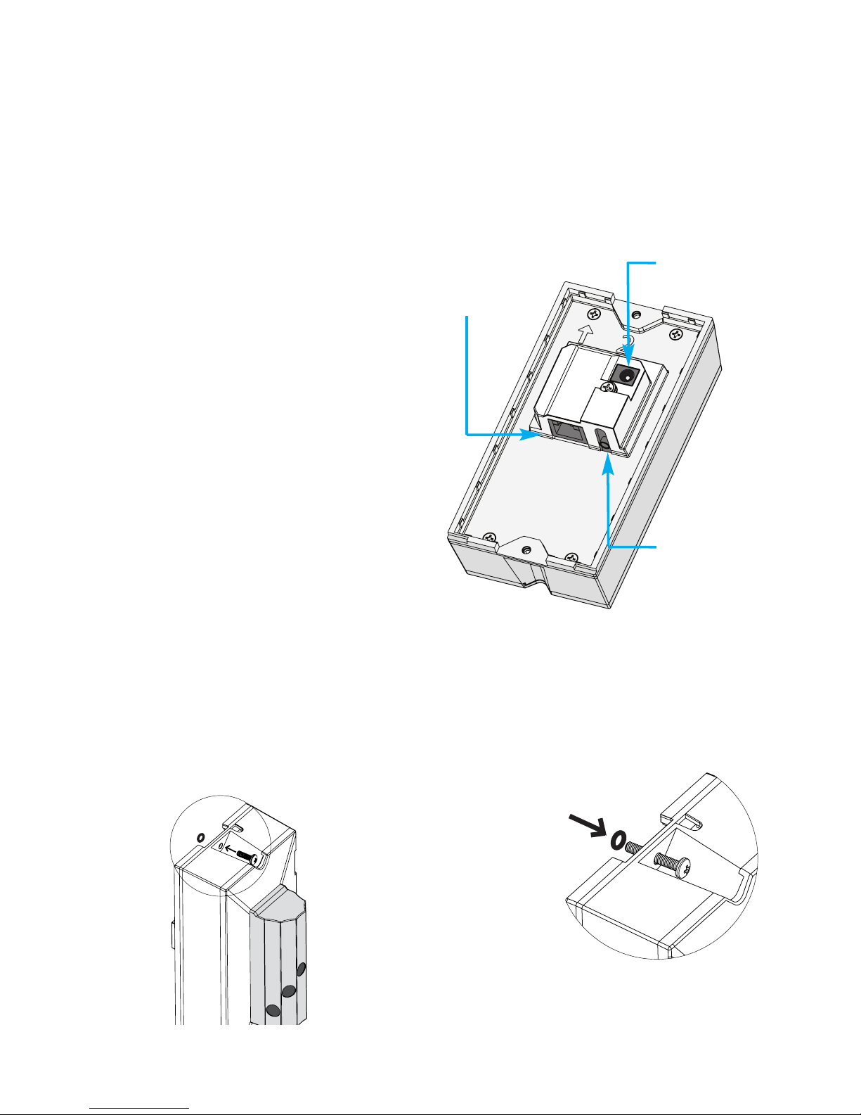
PoE Operation
The camera can be connected
over a network by a CAT-5 Ether-
net cable plugged into the rear of
the camera. If the network sup-
ports PoE, power is supplied di-
rectly via the Ethernet cable. The
camera can also be powered by
a 12volt power supply that is in-
cluded if the network does not
support PoE.
Ethernet
connection
12V DC plug
Audio
connection
(not yet supported)
Two O-rings have been
included to aid in
installations, if needed.
The O-rings are intended to
secure the screws before
attaching the camera to
the wall mount. Insert the
screw into the mounting holes
at the top and bottom of the camera. olling the
O-ring over the tip of the screw will hold it in
place allowing for easier installation.
3
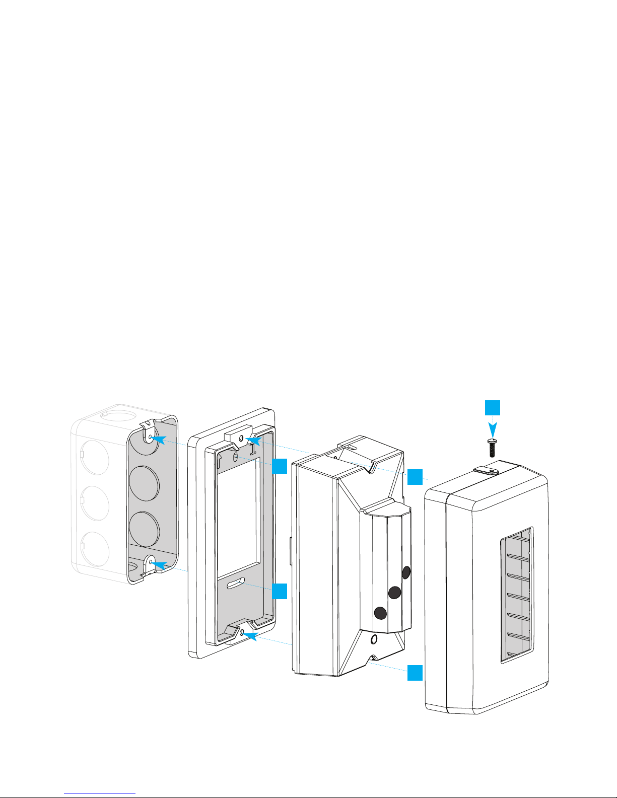
Installing the Camera
A. Place the flush wall mount bracket (1) against a gang box and at-
tach top screw, leaving screw slightly loose.
B. Attach the bottom screw.
C.Using a bubble level, level the mounting bracket, then finish tight-
ening both screws.
D.Feed the Ethernet cable through hole of mounting bracket, and
connect to the Camera (2).
E. Place the camera on the mounting bracket, and secure with pro-
vided screws.
F. Slide the camera cover (3) over the camera and secure with pro-
vided tamper-proof screw.
Note: Do not overtighten or use power too s when attaching
wa mounts.
Junction
Gang Box
Flush Wall
Mount (1) Camera (2)
Camera Cover (3)
B
E
F
A
E
4
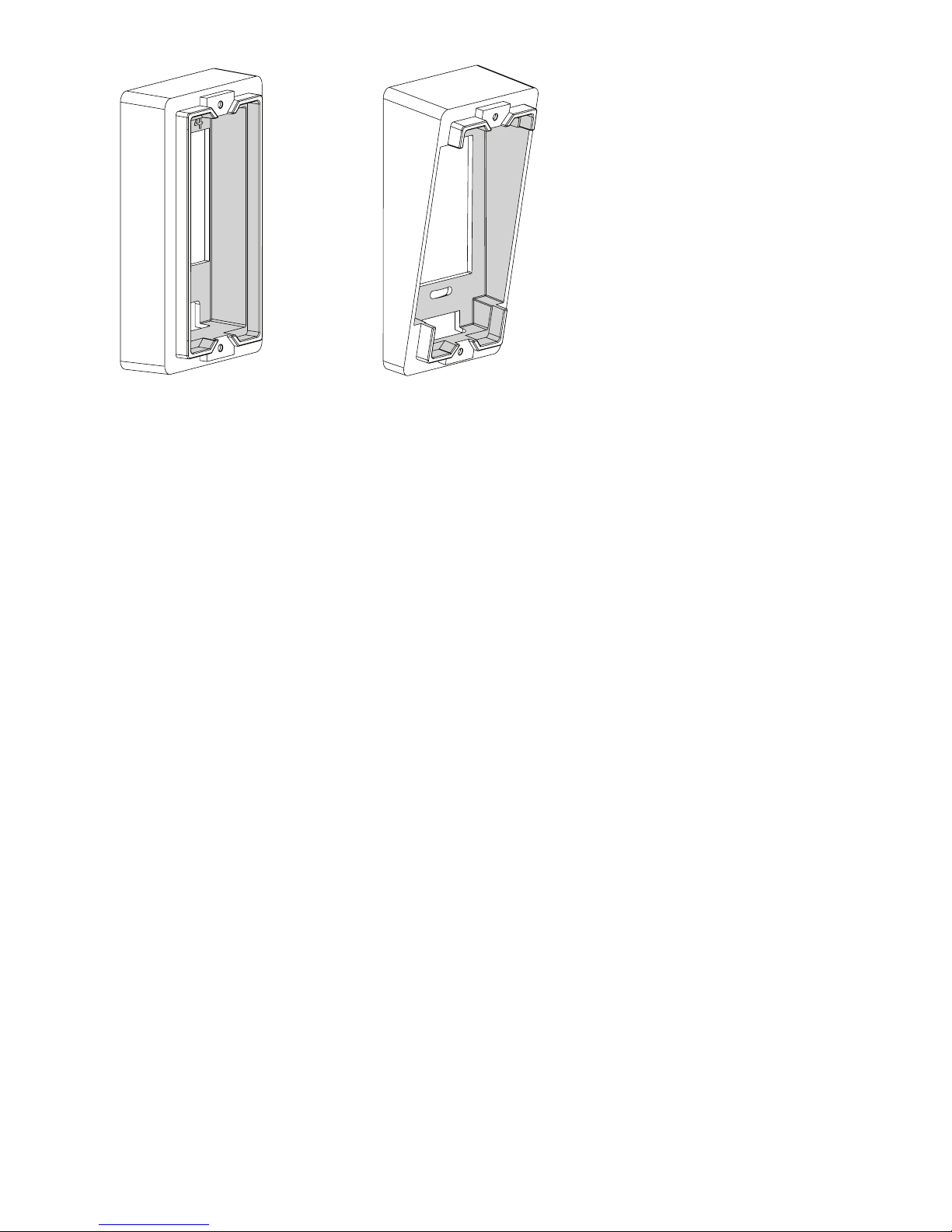
If no Junction Gang Box
is available, the Vertical
Wall Mount (4) for
straight ahead viewing,
or the Angled Wall
Mount (5), for angled-
down viewing may also
be mounted flush to the
wall.
Be sure to use appro-
priate wall anchors (not
included) to secure the
mount to a drywall
surface.
Vertical Wall Mount Angled Wall Mount
Accessories: alternative mounts
Installing the Software
On a network
In order to get the camera operating on a network, software will need to
be installed on a computer that meets the minimum system requirements.
Minimum System equirements:
•Windows 7 or Windows 8
•2.0 GHz CPU (Dual-core
1.8GHz or higher CPU
with 2 GB RAM or higher
recommended)
•2 GB RAM or higher
•200 MB hard drive space
•Display adapter capable of 32-
bit color depth or higher,
512 MB or higher video
memory
•Minimum display resolution
1280 x 720
•10/100 Mb Ethernet adapter
•PoE Switch or 12V DC power
supply (included)
•Internet Explorer or Mozilla
FireFox

5
Software installation
It is necessary that you register your camera as soon as possible at
scallopimaging.com/registration so that you can download and
install the D7-180 Software Installation Driver files.
It is critically important that you download and install these
drivers before operating the camera. The camera will not oper-
ate without installing these files on your computer.
All registered users will be able to remotely download and install all
future camera software upgrades at no charge from the
scallopimaging.com website. We can notify you when future software
enhancements become available.
Accessing the Camera
On a network
Scallop Imaging IP cameras are IPV4LL compliant. If you have a DHCP server
on your network, the DHCP server “router” will assign the camera an IP ad-
dress automatically. If a DHCP server “router” is not on the network, the cam-
era will be assigned a 169.254.x.x address. If you are setting up the camera
without a DHCP server “router” you will need to set your computer to obtain
and IP address.
Examples:
Established network:
1. Set laptop to obtain an IP address automatically.
2. Connect and power all devices.
3. Cameras will show in camera finder with individual 169.254.x.x addresses.
Laptop. Multiple Scallop cameras, PoE switch:
1. Set laptop to obtain an IP address automatically.
2. Connect and power all devices.
3. Cameras will show in camera finder with individual 169.254.x.x addresses.
6
Once you access the camera you
can change its mode from DHCP to
Static. See the network settings sec-
tion for more detail.
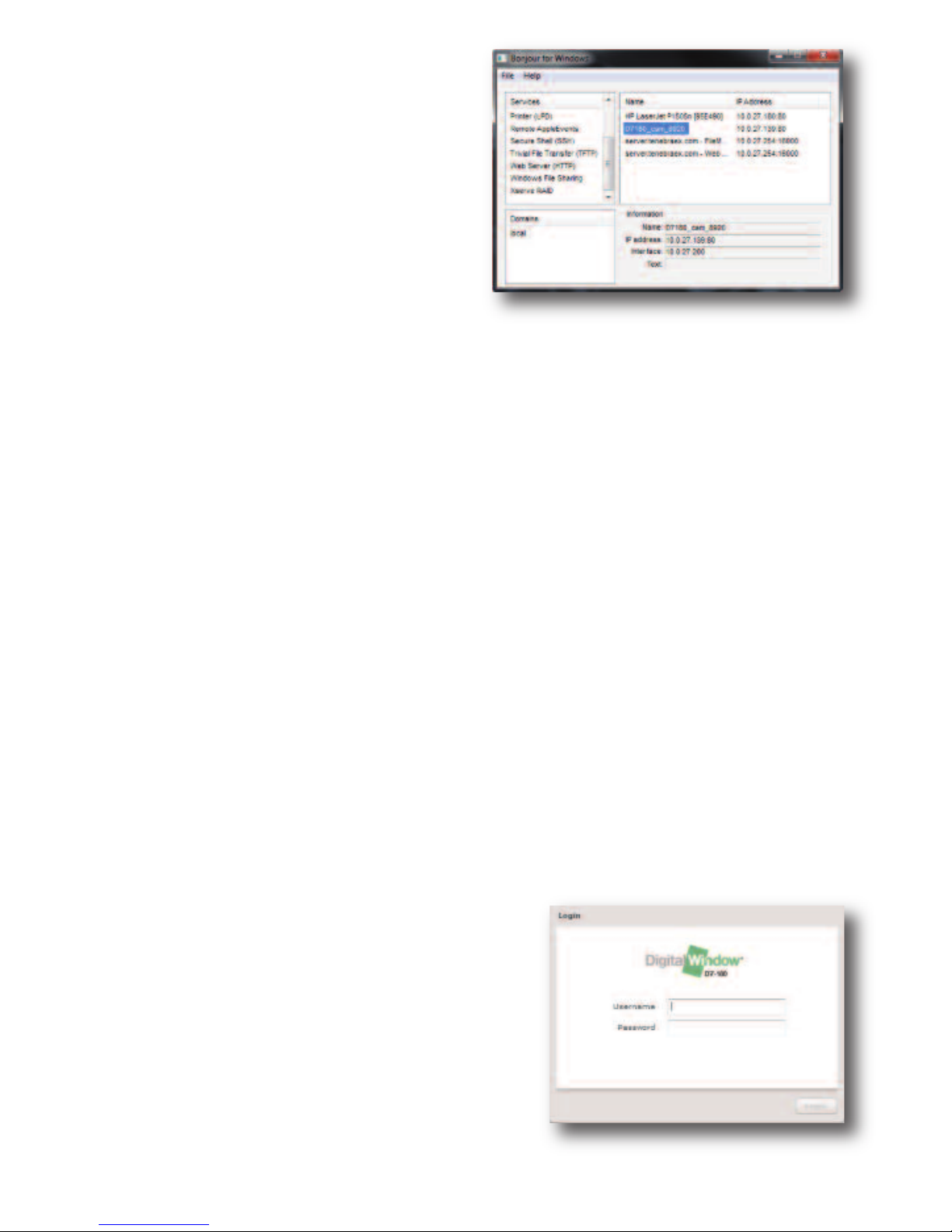
Also provided is a Bonjour for
Windows discovery utility.
This stand-alone program has been
provided for easy access to the
camera.
To use it, simply start the application and a window (above) will appear.
Click on Web Server (HTTP) on the left column and devices with the
Bonjour naming protocol will be shown on the right hand column. Each
D7-180 camera will be named “D7180_cam_****”, and each D7-180XR
will be named “D7XR_CAM_****.” The **** will be the last 4 digits of the
MAC address of the camera. The MAC address can be found printed
on the rear label of each camera.
Note: The Bonjour networking protoco sends and receives net-
work packets on UDP port 5353. The Bonjour installer will configure
the Windows firewall appropriately during installation on supported sys-
tems, but if you have a separate "personal firewall" enabled, you will
need to ensure that UDP port 5353 is open for Bonjour to work cor-
rectly. The Bonjour for Windows discovery utility is subject to change.
Once you have found the camera in the Bonjour for Windows program
simply click on its name and your default browser will open the cam-
era's built-in web interface.
The first window that wi appear wi
be the ogin screen.
You can log on to the camera using the
default username and password.
•The default user name is: admin.
•The default password is: password.
Live Feed Screen
After logging in, you will be brought to the
D7-180/D7-180XR browser site. By default,
the “Live Feed” tab will be activated
If your browser has multiple tool bars open,
and the display resolution is close to the mini-
mum system requirements, the bottom of the
live view page will be cut off.
To obtain the full view of the camera and to avoid scrolling, set the
browser to full screen mode. This can be done by clicking "view" then
clicking full screen, or pressing F11 on the keyboard.
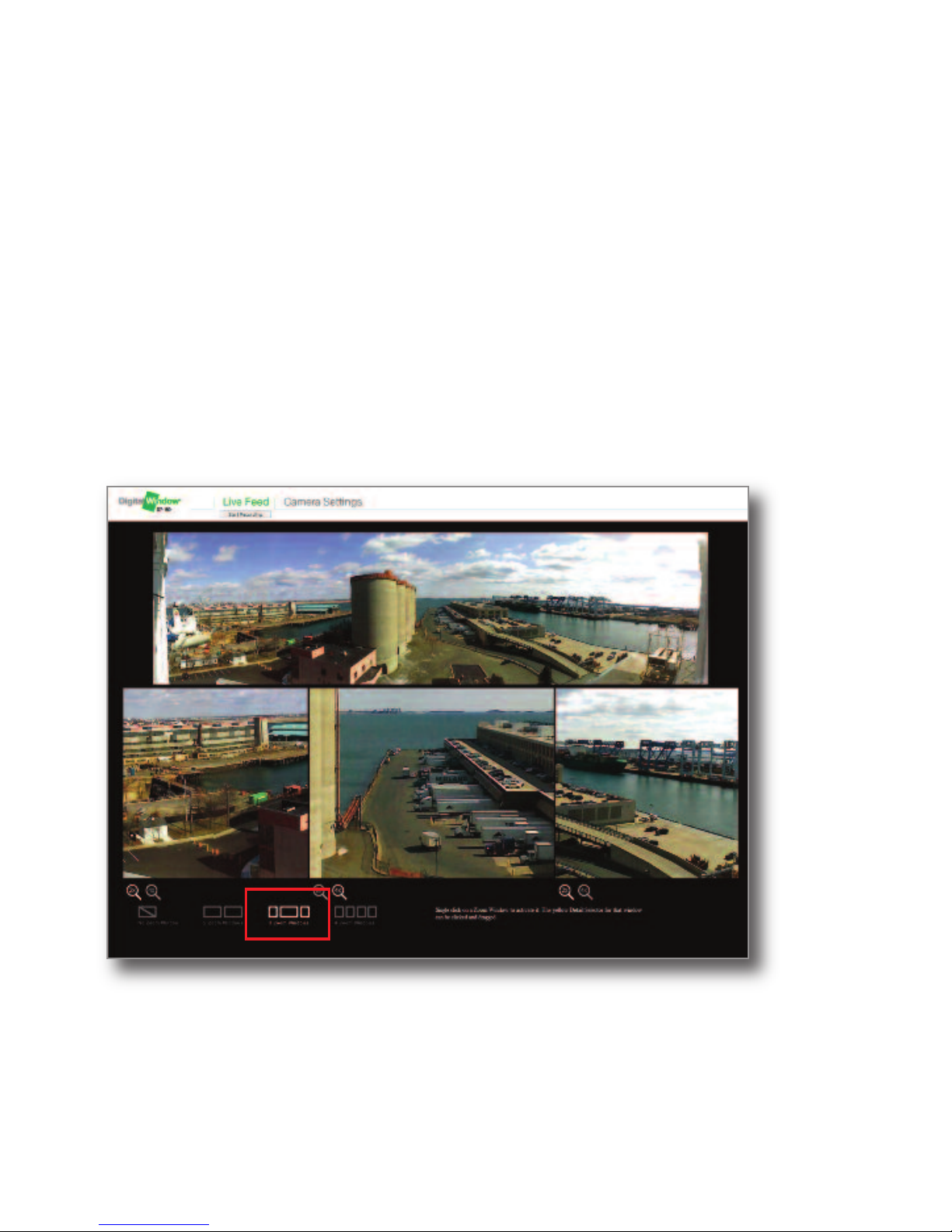
Selecting Zoom Window Views
At the bottom of the page you will find options to configure the zoom
windows. You can choose 0, 2, 3 or 4 zoom windows to appear on the
screen at once.
7
Once you initially log
on to the camera, you
can set up user
accounts.
Setting up user
accounts is discussed
in more detail later in
The Camera Settings
section on page 10.
8
To choose the number of zoom windows you
would like to appear on the screen click on
the icons at the bottom of the screen. Once
chosen the video will change to the zoom
window configuration you have choosen.
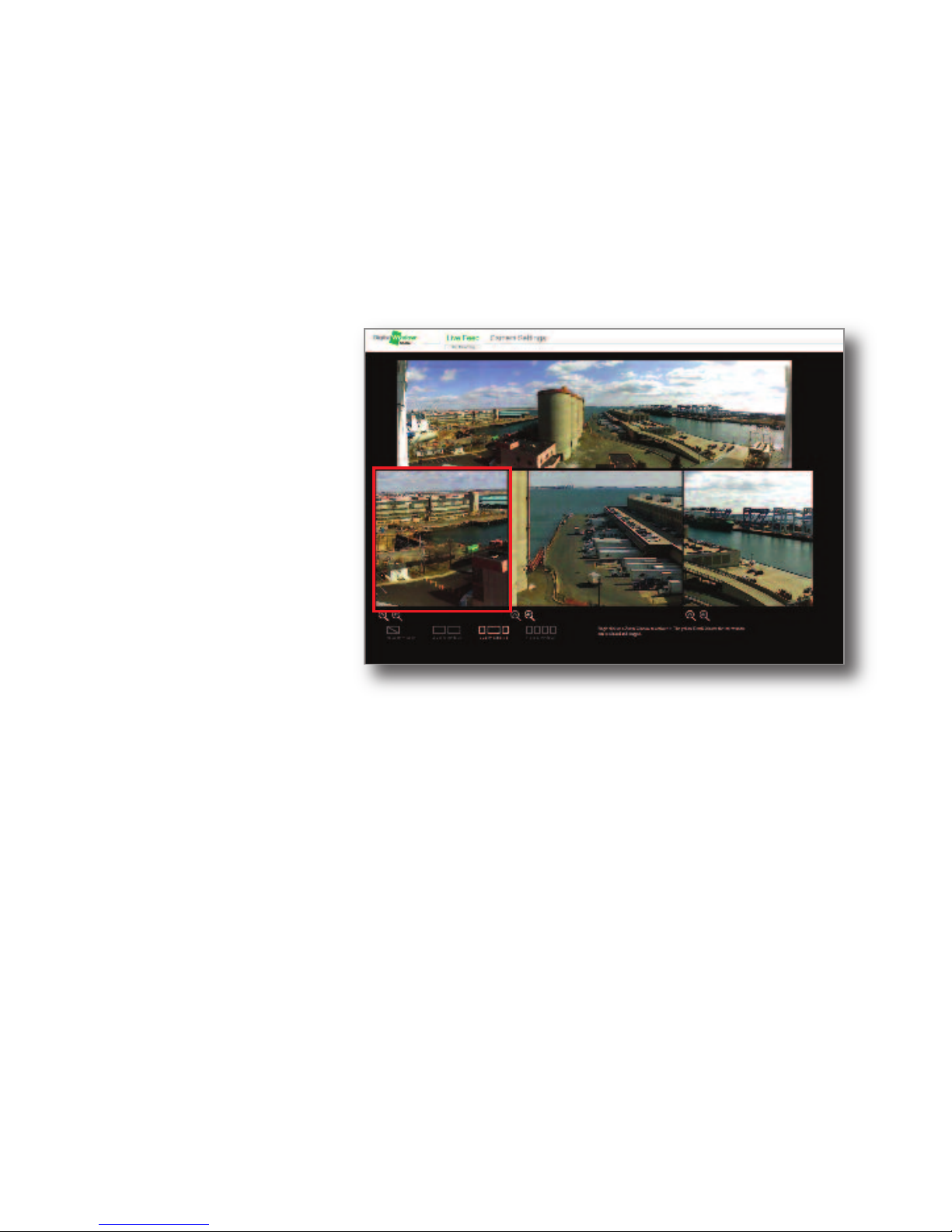
Positioning the
zoom windows:
Click on the zoom
window in the bottom
half of the live feed
window that you wish
to reposition. Once
you have clicked in
the desired zoom
window a yellow box
will appear in the Situ-
ational Awareness
Window (180 degree
view) where the current position of the zoom window is located (see
above):
Once the yellow box appears, you can drag the box to reposition it by
holding down the mouse button and dragging and dropping the box
to the position you want the zoom window to be positioned. Once you
release the mouse button, the zoom window will reposition to that lo-
cation. Do this for each zoom window to obtain views of the area of in-
terest. You can change the positions of the zoom windows anytime.
Live Feed Screen (continued)
Note: The video will
stop playing for 2-3
seconds while the new
zoom windows appear.
Andere Handbücher für D7-180
2
Dieses Handbuch passt für folgende Modelle
1
Inhaltsverzeichnis


