short circuits SENSOR ARRAY Bedienungsanleitung

INSTRUCTION MANUAL
SENSOR ARRAY

SENSOR ARRAY
Contents
The SENSOR ARRAY is just that, an array of sensors. The Motherboard and other Arduino
based microcontroller boards use various inputs and outputs to form functions for a device that
is of some use. The Sensor Array gives the Motherboard access to data about the surrounding
environment. This data can be saved for later, or used to trigger other actions like outputting to a
display, or triggering an alarm.
The sensors available on the Sensor Array are temperature and relative humidity via the DHT11,
sound via a microphone and amplier circuit, and light via a light dependent resistor. We have
also included a Micro SD card slot and a logic converter circuit to convert our microcontroller’s
5V logic to the 3.3V needed for the SD card’s logic.
Circuit
Assembly Instructions
Coding Basics
Projects
Component Index
4
12
20
24
26

Kit Contents
Tools Needed
1 x DHT11 Sensor
1 x Micro SD Card Slot
1 x Microphone
1 x Light Dependant Resistor
1 x LM386 Amp
1 x DIP8 Socket
3 x 100nF Ceramic Capacitors
1 x 47pF Ceramic Capacitor
5 x 10uF Electrolytic Capacitors
1 x 3.3V Regulator HT7533
3 x 2N7000 MOSFETs
9 x 10K Resistors
1 x 10 Ohm Resistor
1 x 10K Potentiometer
11 x Screw Terminals
4 x 5mm M3 Hex Screws
4 x Female/Male Standoffs
1 x Printed Circuit Board
Soldering Iron
Solder
Side Cutters
Screwdriver
Alan Key
0.3 - 0.5mm 2mm
2mm
104
3.3V
5V
U2
C4
Q3-5
R4-9
MK1 RV1
LM386
LDR
DHT22
DHT11
U3
R1
R3
R2
C2 C8
C7
C3
C5
C6
U1
+
+
+
+
+
J2
C10
Sensor Array
LDR
LDR
LDR
MIC
MIC
MIC
CLK
Dout
Din
CS
DHT
DHT
DHT
DHT
DHT
DHT
DHT
DHT
C1
R10
GND
VCC
VCC
GND
J1
473
7533-1
2N
7000
50V 10uF

4
Circuit - Symbols and Designations
Copper power trace
Through hole solder pads
R
C
C
Q
RV
U
U
LDR
J
U
MK
Copper signal trace
Copper trace on back of board
Surface mount solder pads
Resistor
Ceramic capacitor
Electrolytic Capacitor
+
MOSFET
Potentiometer
LM386 Amplier
DHT11 Sensor
Light Dependant Resistor (LDR)
Micro SD Card Slot
Electret Microphone
Voltage Regulator
Mechanical hole
J
Screw terminal
Connected to GND plane
GND
Connected to VCC
+5V
PCB SCHEMATIC DESIGNATION
3
1
2
DHT22
DHT11
+
1
2
3
DAT0
VSS
CLK
VDD
CMD
DAT3/CD
DAT1
DAT2
SHIELD
1
2
3
+

CIRCUIT
Circuit - PCB Design
Ground (GND) Copper Area On Bac
k of PCB
3.3V
5V
U2
C4
Q3-5
R4-9
MK1 RV1
LM386
LDR
DHT22
DHT11
U3
R1
R3
R2
C2 C8
C7
C3
C5
C6
U1
+
+
+
+
+
J2
C10
Sensor Array
LDR
LDR
LDR
MIC
MIC
MIC
CS
Din
Dout
CLK
DHT
DHT
DHT
DHT
DHT
DHT
DHT
DHT
C1
R10
GND
VCC
VCC
GND
J1
These labels are in the wrong
order on v1 of the PCB.
This image is correct.

6
Circuit - Schematic
LDR
LDR
LDR
MIC
MIC
MIC
CS
Din
Dout
CLK
DHT
DHT
DHT
DHT
DHT
DHT
DHT
DHT
GND
VCC
GND
VCC
J1
IO
Terminal Block IO
+5V
+5V
+5V
GND
GND
C2
GND
Vin
Vout
1
2
3
1
2
3
1
2
3
1
2
3
U1
HT7533
10uF
+3.3V
+3.3V
+3.3V
GND
C3
J2
Q3
2N7000
R4
10K
R5
10K
10uF
3.3V Voltage Regulator
3.3V Logic Level Converters
Micro SD Card Slot
DAT0 DATA_OUT
CLK_3v3
DATA_IN_3v3
CS_3v3
VSS GND
CLK
VDD 3.3V
CMD
DAT3/CD
DAT1
DAT2
7
6
5
4
3
2
8
10
1
SHIELD
C10
100nF
CS_3v3
CS_5V
+5V
+3.3V
Q4
2N7000
R6
10K
R7
10K
DATA_3v3
DATA_5V
+5V
+3.3V
Q5
2N7000
R8
10K
R9
10K
CLK_3v3
CLK_5V

CIRCUIT
GND
GND
DHT11 Sensor
Light Dependant Resistor (LDR)
Microphone and Amplifier Circuit
MK1
R2
10K C6
10uF
C5
10uF
RV1
10K
U2
LM386
+
Vcc
3
2
2
4
1
1
85
7
6
BYPASSGAIN
GAIN
Vout
GND
-
R3
10Ω
C8
47pF
C4
10uF
++
+
+
+5V
+5V
+5V +5V
1
GND
IO
U3
DHT11
C1
100nF
R1
10K
VCC
2
4
DH_DATA
DH_DATA
GND
GND
GND
GND
MIC
+5V
GND
C7
100nF

8
Designation
C1, C7, C10
C2 - C6
J1
J2
Q3-5
R1, R2, R4 - R10
R3
RV1
LDR
MK1
U2
U3
Value
100nF
10uF
11 x 2 pos
Micro SD
2N7000
10K
10Ω
10K
5K - 0.5M
-52dB
LM386
DHT11
Name
Ceramic Capacitor
Electrolytic Capacitor
Screw Terminal
Micro SD Card Slot
N Channel MOSFET
Resistor THT
Resistor THT
Resistor THT
Photoresistor THT
Electret Microphone
Amplifier IC
°C/RH Sensor
Footprint / Pitch
2.54mm
2.54mm
C9 47pF Ceramic Capacitor 2.54mm
3.5mm
TO-92
7mm
7mm
3mm
2.54mm
DIP8
U1 HT7533 3.3V Regulator TO-92
Datasheet
Bill of Materials (BOM)

CIRCUIT
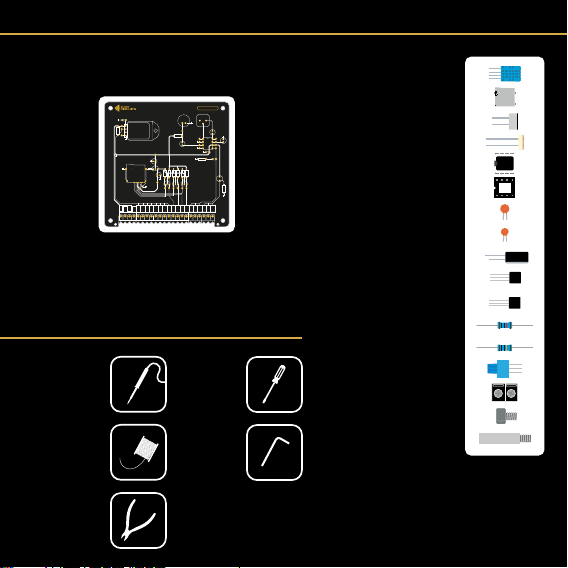
Circuit - SD Card Slot & Circuit
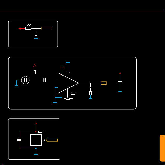
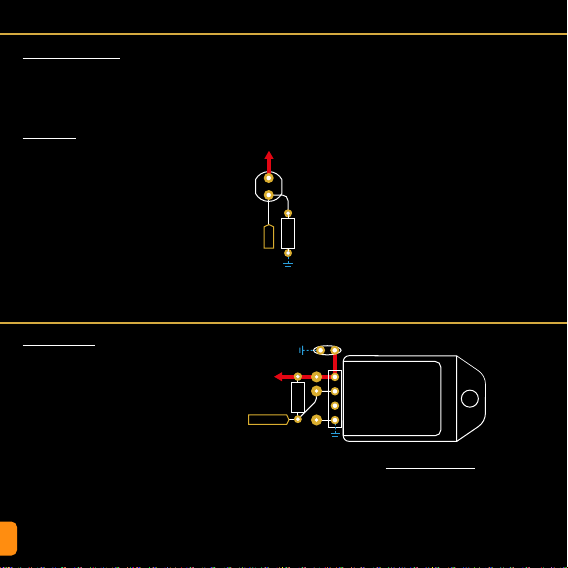
Micro SD Card Slot (J2)
SD Cards can be used to store informa-
tion from sensors or interactions over long
periods of time. You could use it to log the
temperature of a room over the course of a
day, or even a year. The data could then be
imported into a spreadsheet and graphs can
be made! Marvelous. This is just one exam-
ple, but there are many more.
To interface an SD card with a microcontrol-
ler running Arduino code, we need to use SPI
mode. SD cards can interface using a more
complex protocol called SDIO. This is what
mobile phones and cameras use, but it is far
too complex for a microcontroller to manage.
The labels shown on the datasheet and
those on the SD slot’s diagram above are
SDIO pins. They are there for your reference
as datasheets often only mention these. SPI
uses 4 connections; a Chip Select, 2 data
lines, and a Clock Pulse. We have labeled
these from the SD slot’s point of view (the
“slave” in the master slave analogy. See the
Motherboard Manual p29 for more info).
3.3V Voltage Regulator (U1)
SD cards run off 3.3V and so does their log-
ic. Our system runs on 5V, so we use a 3.3V
Voltage Regulator to provide the 3.3V to the
card and to the logic level converter circuitry.
We have used a 7533 for this as it provides
SD Card Motherboard / Uno
CS (Chip Select) Any Pin
Data In (MOSI) D11
Data Out (MOSI) D12
CLK (SCK) D13
+3.3V
Q3-5
2N7000
R4-9
10K
C2
10uF
U1
HT7533
+
+
J2
SD Card Slot
C10
100nF
C3
10uF
Test Point
CS_5V
DATA_IN_5V
DATA_OUT_3v3
CLK_5V
+5V
+5V
GND
GND
GND
GND
GND
DAT0
VSS
CLK
VDD
CMD
DAT3/CD
DAT1
CD
DAT2
Dout
GND
CLK
VCC
Din
SDIOSPI
CS
the 3.3V we need at a max current rating that
exceeds our requirements.
Logic Level Shifting (Q3-5, R4-9)
Logic level shifting is needed when two com-
municating devices read a High (digital 1) at
different voltages.
The SD card regards 3.3V as high, and the
Microcontroller sees anything from 3-5V
as high.
This is ne when the SD card sends a 1 to
the microcontroller, as 3.3V is still considered
High and won’t destroy anything. This is why
DATA_OUT is not converted in our circuit.
The problem arises when the microcontroller
sends a 1 (5V) to the SD card. As the card is
only rated for 3.3V, this can cause damage.
There are a few ways to achieve logic level
shifting. One method is to use two resistors
to create a voltage divider (see Resistors in
the component index). However, this method
can be somewhat unstable and only works
in one direction.
Another method uses N-Channel MOSFETs
with some pull-up resistors. This method is
stable, fast and works in both directions. SD
cards in SPI mode are limited in speed so the
2N7000 works ne. For faster switching use
a dedicated logic level MOSFET.
Arduino, and therefore the Motherboard will
only read SD or SDHC Micro SD cards up
to 32GB. These must be formatted to FAT32.
This can be done by right clicking the SD
card in an explorer window on a Windows
PC, choosing format, selecting FAT32, then
formatting.

10
Circuit - Light Dependant Resistor (LDR)
Circuit - DHT11 Sensor
Light Dependant Resistor
A light dependent resistor is a simple device
that changes resistance depending on how
much light is hitting it. Increasing the light
intensity decreases the resistance.
Resistor (R10)
Because the LDR simply acts as a resis-
tor with varying resistance, connecting it
between 5V and the analog pin of the mi-
crocontroller won’t work. This would just
vary the current that can pass through the
resistor, but the voltage would stay pretty
much the same.
To achieve the effect we need for an accu-
rate reading on an analog pin, (a value be-
tween 0V and 5V), we need to use another
DHT11 Sensor (U3)
The DHT11 is an inexpensive sensor that
detects Temperature and Relative Humidi-
ty. It is a single data line device with some
complicated timing to deal with in the code.
Fortunately there are very useful libraries
available (“DHT Sensor Library” by Adafruit
for example) to handle all the complex stuff,
so you can concentrate on the data itself.
One of the limitations of the DHT sensors
is that they tend to interrupt anything else
that the microcontroller is controlling while
they are transferring data (a icker of the
display while the temperature is being read
for example).
The DHT11 has a more expensive cousin,
the DHT22. This sensor has a better tem-
perature and relative humidity range than the
DHT11, but this is only useful in certain situ-
ations. They are interchangeable though, so
if you nd yourself needing more range, then
swap the DHT11 out for a DHT22.
+5V
GND
GND
DHT22
DHT11
U3
DHT11/22
R1
10K
C1
100nF
DH_DATA
+5V
GND
LDR
R10
10K
LDR
Additional Components
As with any sensitive electronic device, a
bypass capacitor is always useful to smooth
out any noise. Also, the DHT11’s data line
needs to be held high according to its data-
sheet. So a 10K resistor is added between
it and Vcc.
resistor to form a voltage divider. The LDR
we are using has a resistance range some-
where between ~100 and ~0.5M (500K
ohms).
If the LDR has a lot of light shining on it, and
has a resistance value of around 100, the
analog pin would read closer to 5V (as this
is the path of least resistance) and show an
analogRead value of close to 1023.
If the LDR was in complete darkness and
had a resistance value of 500K, the path of
least resistance would be towards GND. This
would result in a value close to 0V and an
analogRead value close to 0.
If there was just enough light for the LDR to
have a resistance of 10K, we would read a
value of 2.5V and an analogRead of ~512.
These values can then be used to control
other functions. Maybe we would like to turn
on an LED when the light level gets too low,
or we could map the value to a range that we
can more easily understand, like 0-100, then
display it on a digital display as a percentage.
Beliebte Hauptplatine Handbücher anderer Marken

Telit Wireless Solutions
Telit Wireless Solutions SL869-3DR Bedienungsanleitung

Gigabyte
Gigabyte GA-9IVDT Bedienungsanleitung

Texas Instruments
Texas Instruments ADS8372EVM Bedienungsanleitung

Commell
Commell MS-C73 Bedienungsanleitung

IBT Technologies
IBT Technologies MB860 Bedienungsanleitung

Nvidia
Nvidia TEGRA DG-04927-001_V01 Bedienungsanleitung


