
SIMALFA G11 HVLP Bedienungsanleitung

15 Lincoln Street Hawthorne, NJ 07506 USA Tel: 973.423.9266 Fax: 973.423.9264 simalfa.com
Parts Desription
1
Setup + Use
2
Cleaning + Maintaining
5
Trouble Shooting
6
Table of Contents
G11 HVLP SPRAY GUN GUIDE

1
PARTS DESCRIPTION
Item Part Number Description Quantity
GS-254G1120 Simalfa G11 | HVLP Spray Gun 2.0mm
01, 02, 03, 04 G11-01-04-2.0 Simalfa G11 | Air Cap 2.0mm
05 G11-05-2.0 Simalfa G11 | Fluid Nozzle 2.0 mm
06 G11-06 Simalfa G11 | Needle Packing Teon
07 G11-07 Simalfa G11 | Needle Packing Nut
08 G11-08 Simalfa G11 | Air Valve Shaft
09 G11-09 Simalfa G11 | O-Ring (9x1) - [Included on Brass Air Valve Body Set]
10 G11-10 Simalfa G11 | O-Ring (10.6x1.65) - [Included on Brass Air Valve Body Set]
11 G11-11 Simalfa G11 | Brass Air Valve Body Set
12 G11-12 Simalfa G11 | Air Valve
13 G11-13 Simalfa G11 | Spring For Valve
14 G11-14 Simalfa G11 | O-Ring (8x1.5) - [Included on Fluid Needle Guide]
15 G11-15 Simalfa G11 | Fluid Needle Guide
16 G11-16-2.0 Simalfa G11 | Fluid Needle 2.0 mm
17 G11-17 Simalfa G11 | Fluid Needle Spring
18 G11-18 Simalfa G11 | Plastic Packing
19 G11-19 Simalfa G11 | Fluid Adjustment Knob
20 G11-20 Simalfa G11 | Pattern Adjustment Valve Set
21 G11-21 Simalfa G11 | Air Adjusting Valve Set
22 G11-22 Simalfa G11 | Air Hose Joint
23 G11-23 Simalfa G11 | Fluid Nipple
24 G11-24 Simalfa G11 | Trigger
25 G11-25 Simalfa G11 | Trigger Pin
26 G11-26 Simalfa G11 | Trigger Washer
27 G11-27 Simalfa G11 | Trigger Locking Ring
31 G11-31 Simalfa G11 | Needle Packing Washer
32 G11-32 Simalfa G11 | Needle Packing Spring
G11-06-07-31-32 Simalfa G11 | Needle Packing Kit (06, 07, 31, 32)
* Not sold separately at this time.
Packing (7, 32, 6, 31)
2
SETUP + USE
Spray Gun Controls + Inputs
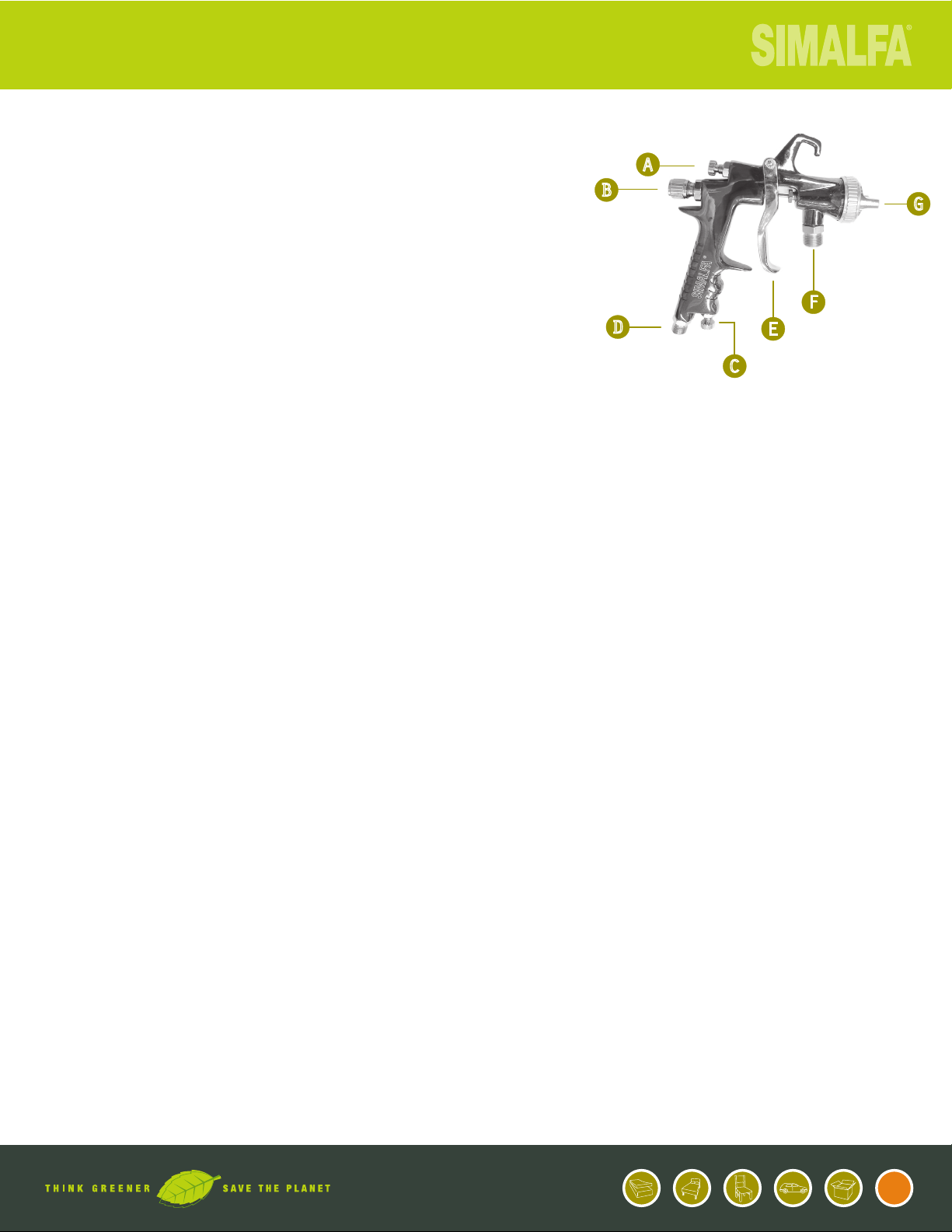
A. Pattern Width Control
This knob controls how Simalfa will come out of the gun. As the knob is
threaded into the gun (tightened), the fan pattern will narrow. As the
knob is unthreaded (loosened), the fan pattern will become wider. It is
important to note that as the fan pattern becomes wider, the air pressure
must also increase to accommodate this.
B. Fluid Knob
This knob controls how much glue will come out of the gun with a full trigger squeeze. As the
knob is threaded into the gun (tightened), the maximum adhesive amount is reduced. As the knob is
unthreaded (loosened), the maximum adhesive amount is increased. A simple rule: less threads = less adhesive,
more threads = more adhesive.
C. Atomization Air Regulator
This is where the atomization air pressure can be adjusted. Turning clockwise decreases atomization air while
turning counter clockwise increases atomization air. However, it is recommended that a wall regulator be installed
for each spray gun to limit the maximum air pressure at the spray gun. Most shop air pressure can be 100+ psi and
that is too high for proper use of an HVLP spray gun.
D. Atomization Air Input
This is where the atomization airline is attached. We suggest using both the atomization air regulator contained
within the Simalfa spray gun and a wall regulator to insure proper atomization. Learn about setting the proper
atomization air in the next section titled “Setting Atomization Air Pressure”.
E. Trigger
Controls the amount of adhesive exiting the spray gun. It’s similar to a gas pedal on a car, the further you pull the
trigger the more adhesive exiting the spray gun.
F. Adhesive Input
This is where the uid hose is attached. 1/2” PVC Fluid Hose and Stainless Steel connectors required.
G. Adhesive Exit Point
This is where the adhesive will exit the spray gun. At this point, all settings such as adhesive volume, pattern width,
atomization pressures come together for application.
A
B
DE
G
C
F
3
Setting Atomization Air Pressure
The key in setting air pressure is understanding that the uid
volume and pattern width a user desires will determine the
PSI required for atomization. That being said, it is impossible
to give an exact setting for all users since each has their own
needs and objectives.
On average, our customers have atomization air pressures set
in the range of (25psi-50psi / about 1.7 - 3.5 Bar). Factors
such as a user’s process, substrates and application will dictate
the required uid volume and pattern width and subsequently
the correct air pressure needed. For example an application
requiring a very small amount of adhesive sprayed in a very
narrow pattern will require low air pressure. There are some
users spraying in the area of 20psi (about 1.4 bar). However,
we also have users where there’s a need for greater uid
volume sprayed in a wide pattern and the air pressure is set at
over 60psi (about 4.13 bar).
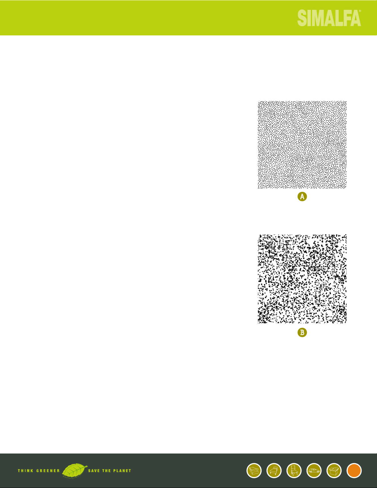
Adjust the air pressure to where the adhesive appears in very
ne droplets. The diagrams on the right illustrate CORRECT
and INCORRECT atomization air pressures as it relates to uid
volume and pattern width.
A. Correct Atomization Air Pressure.
Atomization air is set correctly for the uid volume and
pattern. Simalfa appears in ne droplets to maximize the
efciency and performance.
B. Incorrect Atomization Air Pressure.
Droplets too coarse for the pattern width and uid volume.
Simalfa will not perform as designed.
SOLUTION: Increase air pressure so droplets appear ne, and/
or decrease pattern width, and/or decrease uid volume so
adhesive appears in ne droplets as in diagram A.
SETUP + USE
A
B
4
Recommended Spray Techniques
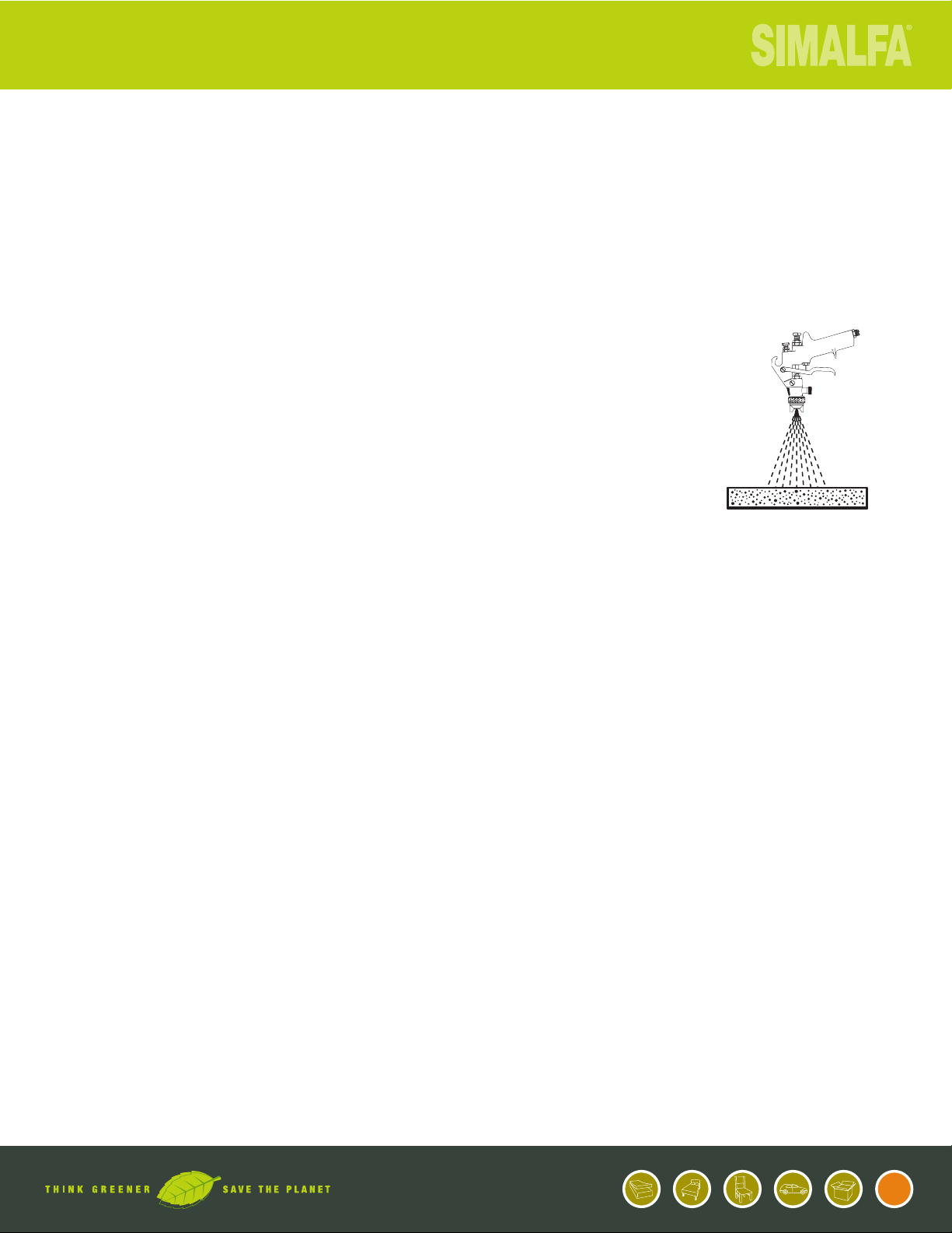
Distance from Substrate.
When applying Simalfa the spray gun should be held at a
distance between 6”-10” (15cm - 25cm) from the substrate.
Pattern Width.
Keep it narrow. A narrow spray pattern gives greater control
over where the adhesive is applied. Wide spray patterns create
waste, mess and overspray.
Angle to Substrate.
Spray Simalfa directly at the substrate, not across or on an
angle. This will insure the most economical application and
reduce any potential for overspray.
Method.
The user should have a sweeping motion left to right and
right to left. A single pass of a light even coverage should be
sufcient. A short pulsating technique will waste adhesive and
cause inconsistencies in the nal bond.
Application.
Application amount is determined by the handling strength
required during the production process and/or the complexity
of the application itself. Simalfa can be sprayed lighter on
easier applications or heavier on more difcult applications. It
is important not to over-apply Simalfa as this creates waste.
Recommended Tips Documents
Better Manual Spraying
Understanding Overspray
SETUP + USE

5
CLEANING +MAINTAINING
WARNING: Prior to any servicing and repair work the spray gun must
be removed from atomizing air pressure and material inputs.
Procedures to always follow:
1. Always swap spray gun at spray station.
2. Always service spray gun immediately. The swapping and/or maintenance of a spray gun should
take about 5 minutes. If maintenance is not immediate and adhesive is allowed to dry, expect
servicing time of about 1 hour, not including the possible interruption in production if gun is not
prepared in a timely fashion.
Things to avoid:
1. Never maintain spray guns while attached to uid line. This will allow adhesive to ow into
the air passageways of the spray gun body causing the compressed air to cure the adhesive,
increasing the maintenance time drastically.
2. Never use any petroleum-based product (i.e. solvent, petroleum jelly, etc.) to clean or lubricate
areas of spray gun where uid may contact.
3. Never submerge spray gun in solvents or other cleaning uids, as this will impair the functional
reliability and efciency of the gun. This will cause more service over time.
Servicing procedures:
1. Remove spray gun from spray system and replace with serviced spray gun.
2. Flush excess adhesive from spray gun using water.
3. Remove air cap, uid nozzle and needle.
4. Flush gun body with water until thoroughly clean. Make sure adhesive does not get inside air
passageways.
5. Clean all parts and remove any dried adhesive on these components and again ush thoroughly.
6. Assemble spray gun. Always install uid nozzle before uid needle. (If parts need replacement,
do it now. We only want fully serviced and repaired guns to be placed into production.)
7. Test for leaks using water. Turn spray gun upside down and ll with water. Check to see if
leaking at nozzle uid nozzle. If leaking replaced both nozzle and needle. (Much easier when
done with water vs. after attaching to adhesive system)
8. Place in a convenient location for next use.
6
TROUBLE SHOOTING
WARNING: Prior to any servicing and repair work the spray gun
must be removed from atomizing air pressure and material inputs.
SYMPTOM CAUSE REMEDY
Adhesive is dripping after trigger is
released (Needle Drag)
Needle Packing Teon (#06) is worn or
damaged.
Clean and/or replace Needle Packing
Teon (#06)
Needle Packing Nut (#07) is too tight. Loosen slightly.
Nozzle (#05) and/or Needle (#16) is
damaged.
Replace.
Foreign material in Nozzle (#05). Remove Nozzle (#05) and clean.
Adhesive leaking at Packing Washer
Nut (#15)
Needle Packing Nute (#07) not tight
enough.
Tighten.
Needle Packing Teon (#06) is worn or
damaged.
Clean and/or replace Needle Packing
Teon (#06)
Air leaking or blowing when in off-
position
Items (#09,10,11,12) is broken.
Replace.
Air Valve Shaft (#08) is stuck. Lubricate or replace.
Spray pattern uneven Air Cap (#01.02,03,04)) hole soiled
at side.
Remove and clean.

15 Lincoln Street Hawthorne, NJ 07506 USA Tel: 973.423.9266 Fax: 973.423.9264 simalfa.com
Descripción de
partes
1
Configuración + Uso
2
Limpieza y mantenimiento
5
Solución de inconvenientes
6
Tabla de Contenidos
G11 HVLP SPRAY GUN GUIDE

1
Item Part Number Description Quantity
GS-254G1120 Simalfa G11 | HVLP Spray Gun 2.0mm
01, 02, 03, 04 G11-01-04-2.0 Simalfa G11 | Air Cap 2.0mm
05 G11-05-2.0 Simalfa G11 | Fluid Nozzle 2.0 mm
06 G11-06 Simalfa G11 | Needle Packing Teon
07 G11-07 Simalfa G11 | Needle Packing Nut
08 G11-08 Simalfa G11 | Air Valve Shaft
09 G11-09 Simalfa G11 | O-Ring (9x1) - [Included on Brass Air Valve Body Set]
10 G11-10 Simalfa G11 | O-Ring (10.6x1.65) - [Included on Brass Air Valve Body Set]
11 G11-11 Simalfa G11 | Brass Air Valve Body Set
12 G11-12 Simalfa G11 | Air Valve
13 G11-13 Simalfa G11 | Spring For Valve
14 G11-14 Simalfa G11 | O-Ring (8x1.5) - [Included on Fluid Needle Guide]
15 G11-15 Simalfa G11 | Fluid Needle Guide
16 G11-16-2.0 Simalfa G11 | Fluid Needle 2.0 mm
17 G11-17 Simalfa G11 | Fluid Needle Spring
18 G11-18 Simalfa G11 | Plastic Packing
19 G11-19 Simalfa G11 | Fluid Adjustment Knob
20 G11-20 Simalfa G11 | Pattern Adjustment Valve Set
21 G11-21 Simalfa G11 | Air Adjusting Valve Set
22 G11-22 Simalfa G11 | Air Hose Joint
23 G11-23 Simalfa G11 | Fluid Nipple
24 G11-24 Simalfa G11 | Trigger
25 G11-25 Simalfa G11 | Trigger Pin
26 G11-26 Simalfa G11 | Trigger Washer
27 G11-27 Simalfa G11 | Trigger Locking Ring
31 G11-31 Simalfa G11 | Needle Packing Washer
32 G11-32 Simalfa G11 | Needle Packing Spring
G11-06-07-31-32 Simalfa G11 | Needle Packing Kit (06, 07, 31, 32)
* Not sold separately at this time.
DESCRIPCIÓN DE PARTES + PRECIOS
Packing (7, 32, 6, 31)

2
CONFIGURACI
Ó
N + USO
Controles de la pistola + Entradas
A. Control del abanico
Esta perilla controla como va a salir el adhesivo Simalfa de la pistola.
A medida que la perilla es enroscada en la pistola (Apretada) el abanico
será más estrecho. A medida que la perilla es desenroscada, el abanico
será más amplio.
Es importante notar que a medida que el patrón del abanico aumenta, la
presión de aire tendrá que ser incrementada.
B. Perilla de Fluido
Esta perilla controla la cantidad de adhesivo que saldrá de la pistola cuando el gatillo se aprieta totalmente. A
medida que la perilla es enroscada en la pistola (Apretada) la cantidad máxima de adhesivo es reducida. A medida
que la perilla es desenroscada, la cantidad máxima de adhesivo será aumentada.
Regla: menos rosca = menos adhesivo, mas rosca = mas adhesivo
C. Regulador presión de aire
Esta perilla es donde se ajusta la atomización del aire en la pistola. Girar la perilla en el sentido de las manecillas
del reloj disminuye la atomización de aire; girar en el sentido contrario a las manecillas del reloj aumentara la
atomización del aire. De cualquier forma se recomienda instalar un regulador de aire para cada pistola para que se
pueda limitar la presión de aire de entrada ya que la mayoría de instalaciones superan los 100 psi.
D. Entrada de aire
Acá es donde se conecta la línea del aire. Sugerimos que se utilicen tanto el regulador de aire de la pistola como el
convencional para asegurar una atomización correcta.
Aprenda mas sobre la forma correcta de atomización en la sección “Ajustando la atomización del aire”
E. Gatillo
Contrala la cantidad de adhesivo que sale de la pistola. Es similar al acelerador de un carro; a medida que se jala el
gatillo aumenta la cantidad de adhesivo que saldrá de la pistola.
F. Entrada de adhesivo
Acá es donde la manguera de adhesivo va conectada. Manguera de ½” y conectores necesarios.
G. Punto de salida de adhesivo
Acá es donde el adhesivo sale de la pistola. Las conguraciones tales como Volumen de adhesivo, abanico, presión
de aire se juntan para dar paso a la aplicación.
A
B
DE
G
C
F
Dieses Handbuch passt für folgende Modelle
2
Inhaltsverzeichnis
Sprachen:
Andere SIMALFA Spritzpistole Handbücher


