Sitron CF12 DC Bedienungsanleitung

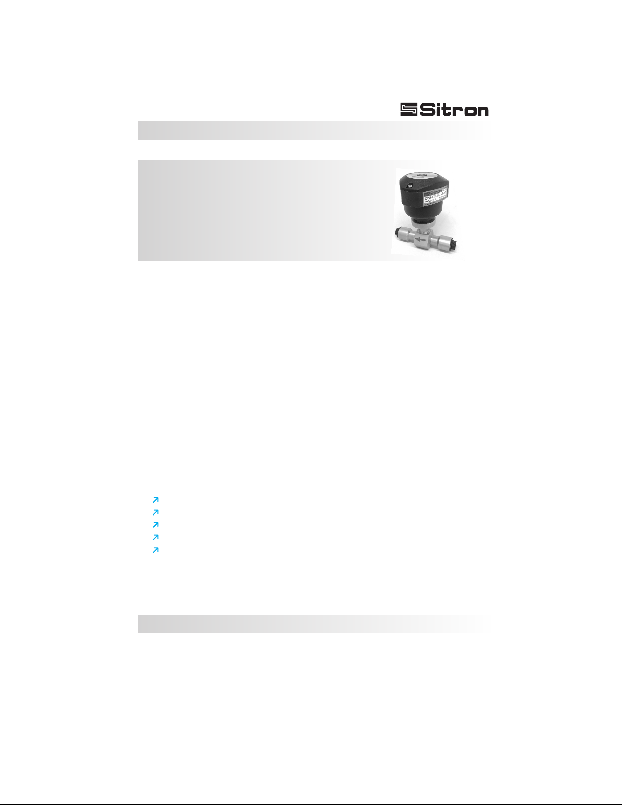
CF12 AC / CF12 DC
Thermal dispersion
Flow switch for Low Flow
USER’S GUIDE
Installation, Operation

03
Contents
Introduction . . . . . . . . . . . . . . . . . . . . . . . . . . . . . . . . . . . . . . . . . . . . . . . . . 4
Models & Dimensions . . . . . . . . . . . . . . . . . . . . . . . . . . . . . . . . . . . . . . . . . 5
Wiring Diagram . . . . . . . . . . . . . . . . . . . . . . . . . . . . . . . . . . . . . . . . . . . . . . 6
CF12 Relay Status Guide . . . . . . . . . . . . . . . . . . . . . . . . . . . . . . . . . . . . . . 8
Installation . . . . . . . . . . . . . . . . . . . . . . . . . . . . . . . . . . . . . . . . . . . . . . . . . . 9
Calibration . . . . . . . . . . . . . . . . . . . . . . . . . . . . . . . . . . . . . . . . . . . . . . . . . 10
Technical Specifications . . . . . . . . . . . . . . . . . . . . . . . . . . . . . . . . . . . . . . 11
Ordering Information . . . . . . . . . . . . . . . . . . . . . . . . . . . . . . . . . . . . . . . . . 12
Trouble Shooting . . . . . . . . . . . . . . . . . . . . . . . . . . . . . . . . . . . . . . . . . . . . 13
Terms & Conditions . . . . . . . . . . . . . . . . . . . . . . . . . . . . . . . . . . . . . . . . . 14
04
Introduction
The CF12 series of thermal flow switches is designed to monitor flow status of
liquids and gases and can also be used to detect level.
A chain of 8 LED's gives the user a visual indication of the flow status of the
switch.
There are two red LEDs that indicate whether or not the unit has detected flow,
a yellow LED to indicate the set point (for increasing or decreasing flows) and 5
green LEDs that indicate the amount of flow beyond the set point of the unit.
The CF12 also includes a di-chromatic (red/green) LED which shows the
switch point status of the unit.
The sensing element and connection of the CF12 are made with 316L S.S. and
can be coated when necessary .
The enclosure is offered in either glass filled nylon or aluminum. All models
can be ordered with a great variety of threaded, flange, or sanitary process
connections.
With the addition of a built in “T-Reducer” connection, the CF12 is now able to
detect flow rates between 3ml and 300ml per minute.
Characteristics
Simple to install.
Excellent low flow sensitivity.
No moving parts-maintenance free reliabity.
Maximum working pressure of 1450 PSI (100 bar).
Fast response time for flow or level (Adjustable from 1-10 seconds).
Thermal dispersion
Flow switch for Low Flow

05
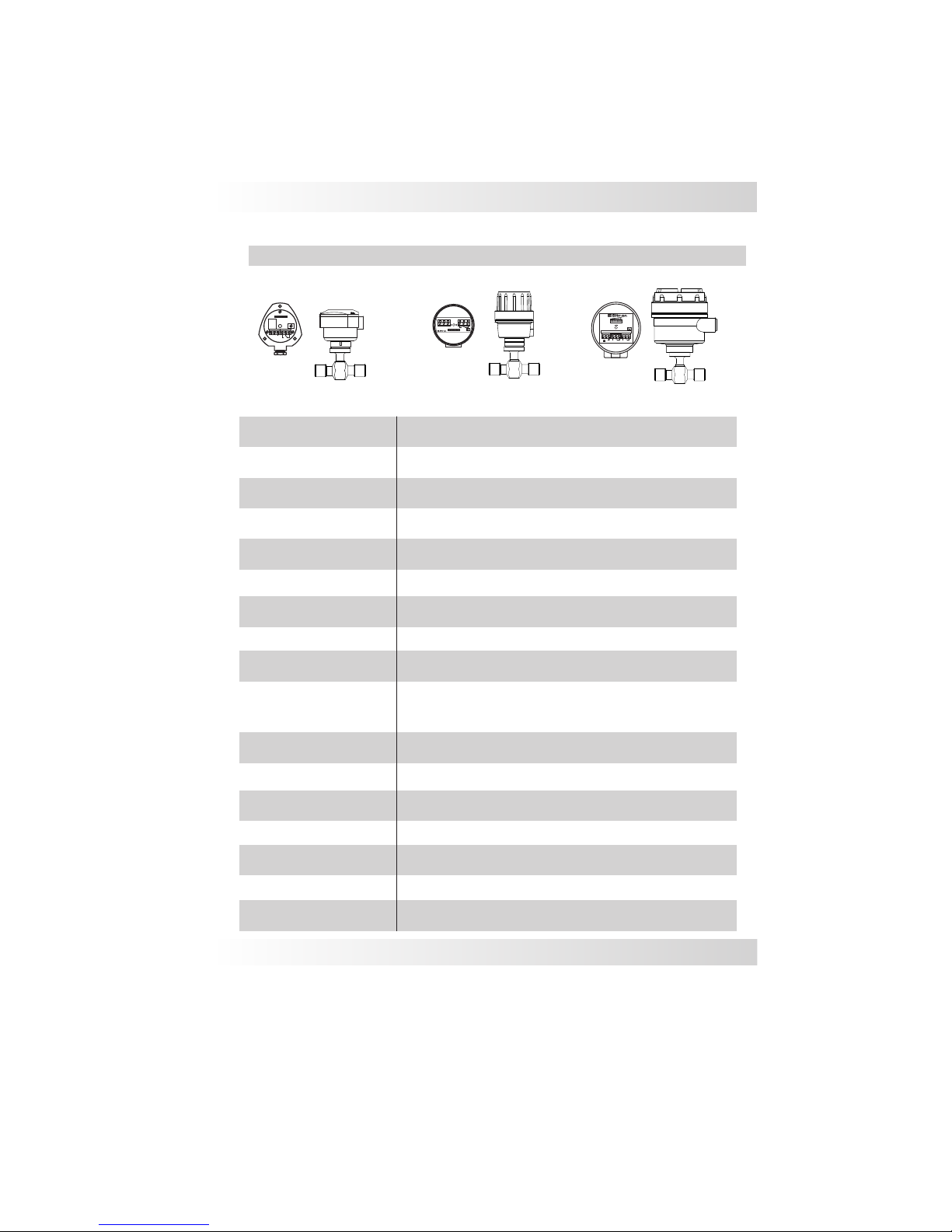
Models & Dimensions
Mounting Options
126mm
130mm
130mm
89mm
76mm
89mm
Nylon-N1 Aluminum-G1 Aluminum-G2
Body Dimension (standard)
6
Hex. 1 1/2"
BSP/ NPT female
49
110
More connections upon request

06
Electrical Connections
Standard Connection w/
2 meters of Cable
+
_
Bargraph (B1)
Bargraph (B1)
Adjust (P1)
Adjust (P1)
Central LED Status (L1)
(Red/Green)
Central LED Status (L1)
(Red/Green)
Adjust
CF 12 DC
Adjust
Red
White (NC)
Green and
Yellow
or solid Yellow
Blue (common)
Green (NO)
Black
Power
Supply
Contacts
Ground
CF 12 AC
2000mm
1
2
Connector
12mm
NO or NC
contact
2000mm
1
2
Connector
12mm
+
++
_
__
NO or NC
contact
Nylon Enclosure (N1)
M12 Connector Optional
M12 Connector Optional
1 - Power Supply (+)
2 - Power Supply (-)
3 - Ground
4 - NO Contact
5 - Common
6 - NC Contact
1 - Power Supply
2 - Power Supply
3 - NO Contact
4 - NC Contact
5 - Common
1 - Power Supply (+)
2 - Power Supply (-)
3 - NO Contact
4 - NC Contact
5 - Common
1
1
5
5
2
2
3
3
4
4

07
Electrical Connections
Aluminium Enclosure (G1/G2)
2SPDT
Bargraph (B1)
Flow 100 %0
+
-
1 2 345 6 7 9
8
CF12
+
_
1 2 3 4 5 6
Adjust
1SPDT
Bargraph (B1)
G2
G1
1 - Power Supply (+)
2 - Power Supply (-)
3 - Ground
4 - NO Contact
5 - Common
6 - NC Contact
(P1) - Set Point Potentiometer Adjust
(B1) - 8 LED´s Bargraph: Red LED
Yellow LED
Green LED
(L1) - Central LED - Green: With flow
Red: No flow
1 - Power Supply (+)
2 - Power Supply (-)
3 - Ground
4 - NO Contact
5 - Common
6 - NC Contact
7 - NO Contact
8 - Common
9 - NC Contact
Central LED Status (L1)
Red/Green
Adjust (P1)
Central LED Status (L1)
Red/Green
Adjust (P1)
( )
( )
( )
( )

08
Sentido Fluxo
Sentido Fluxo
CF12 Relay Status Guide
Application Condition
No Flow
Flow
LED Status
RED
GREEN
Set Point
OFF
ON
CF12 SPDT
Status
NO (4) NC (6)
C (5)
C (5)
NO (4) NC (6)

09
Installation
Fig. 3
Pump
Fig. 2
Fig. 1
5xØ
Flow direction
1/2 meter
Sentido Fluxo
Fig. 4
Checks:
The flow switch must be installed so that the flow
direction follow the flow direction description tag.
1) Its recommended that the flow switch is
installed with a distance of ½ a meter of the pipe
bent where the flow enters and 5x times the
diameter of the pipe where the flow exits, enabling
it to have an accurate reading (Fig. 1).
Verify that the installation point isn’t near any
connections, valves, elbows or anything similar,
this can cause errors in the reading of the probe
due to turbulence in the pipe.
2) It is important that the flow switch is not installed
at the highest point in the pipe run or in a location
where there is the risk of air accumulating in the
pipe. Keep in mind that the ideal mounting
location is where the pipe is always full. This will
ensure that the switch is always immersed in the
flow. (Fig. 2 correct)
3) In pipes that have pressure pumps or retention
valves, we recommend that the probe be installed
before the pump due to the fact that it will have
less turbulence. (Fig. 3)
4) Confirm that the wire connections are correct
and that the available power supply is compatible
with the CF12 unit.
5) Verify that the operating pressure and
temperature of the process corresponds to the
operating parameters of the CF12 unit.
Do not expose the CF12 to excessive heat and
rain, avoid damaging the performance by making
adequate protection (Fig.4)
Flow direction
Flow direction

10
Calibration
Adjust
Adjust
0% 100%
BARGRAPH Lights ON
Set Point
0% 100%
BARGRAPH Lights Off
Set Point
Led Status
Red
Led Status
Blinking
To Start:
1 - Remove the enclosure lid (Note: the screws are self-retaining)
2 - Start the power supply and wait 5 minutes until the CF12 is active and has reached a
stable point within the medium.
3 - Let the regular or desired flow reach its point of normal operation.
Calibration for Flow / No Flow:
1 - Set the flow rate at the normal range of operation.
2 - Turn the potentiometer counter-clockwise until the central LED turns red.
3 - With the central LED red, turn the potentiometer clockwise until the central LED
changes to a blinking green state.
4 - Continue to turn the potentiometer clockwise until the first 3 green LEDs in the bar
graph turn on.
Set Point Adjustment:
The flow switch can be adjusted to indicate either increasing flow, or decreasing flow at
a specific set point within 3ml to 300ml/m.
It is important to determine the specific set point at which the flow switch should activate
or de-activate.
11
Technical Specifications
CF12DC / AC
Flow 100 %0
+
-
1 2 345 6 7 9
8
1 2 3 4 5 6
Repeatability
Application
Operating Voltage
Current Consumption
Electrical Connection
Operating Temperature
Gradient Temperature
Set Point Range
Output
Flow Rate Indication
Max Pressure
Accuracy
Response Time
Enclosure Material
Wetted Material
Class Protection
Process Connection
+/- 10%
1 to 10s
15ºC/min
Liquid: 3ml to 300ml/min
+/- 1% setpoint
Cable gland w/ 2000mm cable, M12 connector or ½” NPT
Red led - flow is below setpoint
Yellow led - flow is at setpoint
Green led - flow is above setpoint
1450 PSI (100 Bar)
IP 65 - Nylon (N1)
IP 66 - Aluminum (G1/G2)
Glass filled nylon / Aluminum painted
316L Stainless Steel
1/4" to 1/2” BSP or NPT (others upon request)
14 to 176º F (-10 to 80ºC)
Low Flow monitor for liquids
DC: 24 VDC (+/-10%)
AC: 85-264Vac (50/60hz) & 125Vdc
+/- 100mA
Relay (SPDT) 5A - 250Vac (N1/G1)
2 SPDT 5A-250VAC - G2
N1 Enclosure
G2 Enclosure
G1 Enclosure
Dieses Handbuch passt für folgende Modelle
1
Inhaltsverzeichnis


