SJE Rhombus VARIOspeed Micro Bedienungsanleitung

VARIOspeed Micro®
User Manual
22650 County Highway 6
n
PO Box 1708
n
Detroit Lakes, MN 56502
Phone 218-847-1317
n
Fax: 218-847-4617
www.sjerhombus.com
WARNINGS
Failure to read and understand the information provided in this manual may result in personal injury or
death, damage to the product or product failure. Please read each section in its entirety and be sure
you understand the information provided in the section and related sections before attempting any of
the procedures or operations given.
Failure to follow these precautions could result in serious injury or death. Keep these
instructions with warranty after installation. This product must be installed in accor-
dance with National Electrical Code, ANSI/NFPA 70 so as to prevent moisture from
entering or accumulating within the controller housing.
See additional specifications on page 6 of this manual.
ELECTRICAL SHOCK HAZARD
Disconnect power to the VARIOspeed®MICRO VFD drive and wait 10
minutes before removing the terminal cover.
A qualified service person must install and service this product according
to applicable codes and electrical schematics.
EXPLOSION OR FIRE HAZARD
Do not use this product with flammable liquids. Do not install in
hazardous locations as defined by National Electrical Code,
ANSI/NFPA 70.
• Lethal voltages are still present inside the VARIOspeed®MICRO VFD drive after power
is disconnected. Wait 10 minutes to allow internal capacitors to fully discharge before
attempting to connect or disconnect wire or to service this equipment.
• Do not connect incoming power to motor terminals U, V, W. doing so will result in
irreversible damage to the drive.
• Do not connect power to this equipment if it has been damaged or has any missing parts.
• Do not apply power to the VARIOspeed®MICRO VFD drive with the terminal cover
removed.
• Verify that the incoming voltage supply is 230 VAC before applying power to the unit.
• The VARIOspeed®MICRO VFD drive contains no serviceable parts, do not attempt to repair
this equipment.
• The VARIOspeed®MICRO VFD drive must be grounded at the grounding terminal according
to N.E.C. Refer to the electrical connection on page 12.
• The VARIOspeed®MICRO VFD drive has been designed for indoor mounting only. Use the
optional NEMA 3R model for outdoor installations.
• Do not install in ares with: excessive or conductive dust, corrosive or flammable gas,
moisture or rain, excessive heat, regular impact shocks or excessive vibration.
• Do into install in areas where ambient temperature exceeds 40ºC (104ºF).
• HOT! Heat sink temperature may rise to 90ºC (194ºF). Do NOT touch heat sink.

Table of Contents
Introduction .................................................................................................2
Receiving and Preliminary Inspection ........................................................3
Specifications..............................................................................................4
System Setup Diagram for Deep Well Submersible .................................5
System Setup Diagram for Pressure Booster ............................................6
Pressure Tank/Pressure Relief Valve/Low Pressure..................................7
Outline Dimensions.....................................................................................8
Removing the cover to access the terminal blocks....................................8
Mounting .....................................................................................................9
Terminal Wiring Description......................................................................10
Grounding Method....................................................................................11
Filter Options ............................................................................................11
Display and Function Keys Overview.......................................................12
Display Description ...................................................................................12
Function Keys Operation ..........................................................................13
Changing the Set Pressure ......................................................................14
Changing Parameters...............................................................................14
Parameter List ..........................................................................................15
Detailed Parameter Functions ..................................................................16
Fault and Alarm Display & Solutions........................................................18
Causes of Malfunction/Troubleshooting ...................................................18
Warranty Information ................................................................................19
SJE-Rhombus®VARIOspeed®Micro Controller User Manual 1

Introduction
Congratulations, and thank you for your purchase of a VARIOspeed®MICRO series VFD. These
drives are indoor wall-mountable units designed for controlling water pumps in either deep well
applications, or pressure boosting centrifugal pump applications.
Product range
The VARIOspeed®MICRO D & D PLUS in either the 1hp or 2hp size are designed for deep well
submersible pumps and centrifugal pressure booster pumps using 230V single phase incoming
power, and are capable of controlling either single phase or three phase pumps by setting the
appropriate parameters.
Product Features
All VARIOspeed®MICRO series drives have a built-in PID function (non-adjustable) that varies
the speed (Hz) of the pump and provide optimal control for maintaining a constant pressure in a
variety of pumping applications. The information included in this manual will help you maximize the
performance of your VARIOspeed®MICRO VFD, and ensure safe operation of your pump system.
Please keep this manual for future reference.
2SJE-Rhombus®VARIOspeed®Micro Controller User Manual

Receiving and Preliminary Inspection
Included in the box:
1. The VARIOspeed®MICRO VFD
2. Pressure transducer (0-145 PSI range – ¼” NPTM) with 20 ft. of cable
3. Transducer cable
4. Strain reliefs (1 x 0.5”, 2 x 0.75”)
5. User manual
6. Wall mounting bracket (4 screws included)
7. Quick start manual
Verify that all components are included and the VARIOspeed®MICRO VFD model number is
correct.
WARNING: Do not connect power to this equipment if it’s been damaged or has any missing parts.
SJE-Rhombus®VARIOspeed®Micro Controller User Manual 3

4SJE-Rhombus®VARIOspeed®Micro Controller User Manual
Specifications
VARIOspeed®MICRO D (1HP) MICRO D PLUS (2HP)
Input rating
Voltage (V) 1Φ, 200V - 240V, 50/60 Hz
Power (W) 4,300W 5,400W
Current (A) Max. 19.5A Max. 24.5A
Minimum Size
Circuit Breaker 30A (2 Pole) 30A (2 Pole)
Output rating
*Voltage (V) 1Φ, 220V 3Φ, 220V 1Φ, 220V 3Φ, 220V
Power (kW/HP) 0.75kW
(1 HP)
1.5 kW
(2HP)
1.5 kW
(2HP)
2.2 kW
(3HP)
Max. Rated Current (A) Max. 11A Max. 14A
Max. Pump FLA 0-9A 0-12A
Frequency (Hz) 20~80Hz 20~60Hz
Operation
Pressure Range 1-69 PSI
Control Method PID control (Proportional + Integral + Derivative)
Environment
IP Rating IEC-529 IP31
Pollution Degree Pollution Degree 2
Operating Temperature 0ºC ~ +50ºC
Storage Temperature -10ºC ~ +60ºC
Ambient Humidity Less than 95%, Non-condensing

System Setup Diagram for Deep Well Submersible
SJE-Rhombus®VARIOspeed®Micro Controller User Manual 5

System Setup Diagram for Pressure Booster
6SJE-Rhombus®VARIOspeed®Micro Controller User Manual

Pressure Tank/Pressure Relief Valve/Low Pressure
To maintain constant pressure and prevent frequent startup, a small-capacity pressure tank is need-
ed in the system (refer to the minimum capacity of pressure tank table below). The VARIOspeed®
MICRO VFD may use a pressure tank of a larger capacity than listed on the table blow.
Minimum Capacity of Pressure Tank
Flow Rate (GPM) Tank Size
(Total Capacity)
Less than 12.0 4 Gallons
More than 12.0 8 Gallons
Pre-Charge Pressure
1. Initial charge pressure should be at least 70% of the system pressure (Set pressure).
2. To maintain the optimum pressure level, check the air pressure in the tank regularly.
Set Pressure (PSI) Initial Charging
Pressure (PSI)
50 (default) 35
55 39
60 42
65 46
A Pressure Relief Valve Must be Installed.
A pressure relief valve MUST be installed as close as possible to the pump discharge and plumbed
to a drain able to handle the full flow of the pump in the event of a malfunction.
WARNING!
Failure to use a pressure relief valve could result in burst pipes and flooding if a system failure should occur.
Low Pressure Switch Shutdown (optional)
A pressure switch may be used to shut down the pump on low pressure. This switch will open on low
pressure and stop the pump from operating with insufficient water supply. (See pg 12 for electrical
connections.)
SJE-Rhombus®VARIOspeed®Micro Controller User Manual 7
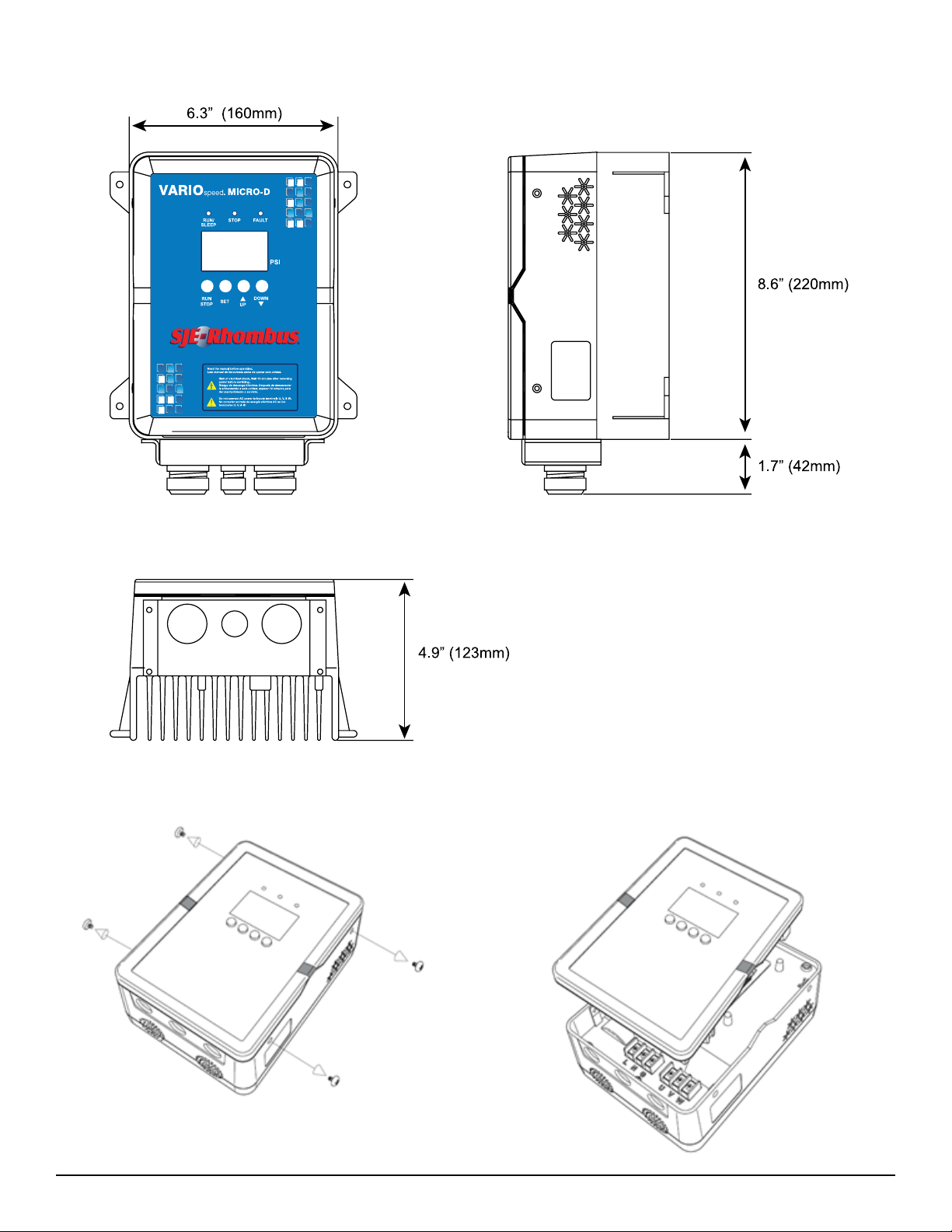
Outline Dimensions
Removing the cover to access terminal blocks
8SJE-Rhombus®VARIOspeed®Micro Controller User Manual
Inhaltsverzeichnis
Andere SJE Rhombus Prüfgeräte Handbücher

Beliebte Prüfgeräte Handbücher anderer Marken

SMART
SMART KANAAD SBT XTREME 3G Series Bedienungsanleitung

Agilent Technologies
Agilent Technologies BERT Serial Bedienungsanleitung

Agilent Technologies
Agilent Technologies N3280A Bedienungsanleitung

Vernier
Vernier Go Direct Voltage Bedienungsanleitung

Lifeloc
Lifeloc R.A.D.A.R. Bedienungsanleitung

Fluke
Fluke T5-600 Bedienungs- und Montageanleitung


PCB Piezotronics
PCB Piezotronics 8159-0112A Bedienungsanleitung

BW Technologies
BW Technologies MicroDock II Bedienungsanleitung

Sun Nuclear
Sun Nuclear 1027 Bedienungsanleitung

Biomark
Biomark HPR LITE READER Bedienungsanleitung

Hioki
Hioki 3169-20 Bedienungsanleitung

Ashcroft
Ashcroft ATE-100 Bedienungsanleitung