Solarton Metrology SI3300 Betriebsanleitung

4-20mA/DC-Digital Display
The SI3300 is a member of the SI3000 Readout Family.
All members of the family are marked SI3000 on the front panel.
This manual is specically for the SI3300 Model with 4-20mA/DC Voltage Inputs
SI3300
user and installation manual
4-20mA/DC-Digital Display

Index
502810 issue 6
Index
Section Title Page
6.11 Display Menu Screen 1 . . . . . . . . . . . . . . . 25
6.12 Display Menu Screen 2 . . . . . . . . . . . . . . . 26
6.13 Utilities Menu . . . . . . . . . . . . . . . . . 27
6.14 Password Menu . . . . . . . . . . . . . . . . 28
6.15 Password Entry . . . . . . . . . . . . . . . . . . . . 29
6.16 Utilities Menu (Factory Default Restore) . . 30
6.17 Operator Screen . . . . . . . . . . . . . . . 31
6.18 X Y Mode . . . . . . . . . . . . . . . . 32
6.19 Logging Menu Page 1 . . . . . . . . . . . . 33
6.20 Logging Menu Page 2 . . . . . . . . . . . . 34
7.0 RS232 User Input Commands . . . . . . . 35
7.1 RS232 User Input Command Details . . . . 36
7.1 RS232 User Input Command Details (cont.) . 37
7.1 RS232 User Input Command Details (cont.) . 38
7.2 RS232 Output Formats . . . . . . . . . . . . . . . . 40
8.0 Interface Connections . . . . . . . . . . . . 41
8.1 I/O Connector . . . . . . . . . . . . . . . 41
8.2 Communications Connector RS232 . . . . 42
8.3 Power Connector . . . . . . . . . . . . . 42
8.4 Analogue Voltage and Current Inputs . . . . 43
9.0 Technical Specifications . . . . . . . . . 44
Return Of Goods
Solartron Sales Offices
Section Title Page
1.0 Index . . . . . . . . . . . . . . . . . . . . . 1
2.0 Safety Summary . . . . . . . . . . . . . . . . 2
Warnings and Cautions . . . . . . . . . . . 2
3.0 Service and Repair . . . . . . . . . . . . 4
4.0 Bench Mounted or Installed into a Panel . . . 5
4.1 BenchMountedwithassociatedSolartronProbes
and power supply . . . . . . . . . . . . . . . 5
4.2 Panel Mounting . . . . . . . . . . . . . . 6
4.3 Panel Dimensions . . . . . . . . . . . . . 7
4.4 Assembly Dimensions . . . . . . . . . . . 8
5.0 Display Panel . . . . . . . . . . . . . . . . 9
5.1 Layout of Front Panel . . . . . . . . . . . . 9
5.2 Layout of Rear Panel . . . . . . . . . . . . 10
5.3 Overview of Features . . . . . . . . . . . . . . 11
6.0 Operating Screen . . . . . . . . . . . . . . 13
6.1 MENUS and SETUPS . . . . . . . . . . . . 14
6.2 Probe Menu Channel A . . . . . . . . . . . . 15
6.3 Probe Menu Channel B . . . . . . . . . . . . 16
6.4 Measurement Menu Page 1 . . . . . . . . . . . . 17
6.5 Measurement Menu Page 1 (cont.) . . . . . . 18
6.5.1 Measurement Menu Page 1 (cont.) . . . . . . 19
6.6 Measurement (Distance) Menu Page 2 . . . . 20
6.7 Measurement (Angle) Menu Page 2 . . . . . . 21
6.8 Limit Menu . . . . . . . . . . . . . . . . . . . . . 22
6.9 Input/Output Menu . . . . . . . . . . . . . . . 23
6.10 Serial Port Menu . . . . . . . . . . . . . . . 24
1

2.0 Safety Information
502810 issue 6
2.0 Safety Information
Terms in this Manual
WARNING statements identify conditions or practices that could result in personal injury or loss of life.
CAUTION statements identify conditions or practices that could result in damage to the equipment or other property.
Symbols in this Manual
This symbol indicates where applicable cautionary or other information is to be found.
Service Safety
This equipment has been designed and tested to meet the requirements of the Low Voltage Directive (1997) and has been supplied in a safe condition.
This manual contains information and warnings that must be followed by the user to ensure safe operation and to retain the apparatus in a safe condition.
Power Source
24v +/-10% DC 0.625A
2

2.0 Safety Information (cont.)
502810 issue 6
2.0 Safety Information (cont.)
3
WARNINGS:
Do not operate in an explosive atmosphere
Do not remove covers or panels
To avoid personal injury, do not remove covers and panels. Do not operate the equipment without the covers and panels fitted. There are no internal
adjustments required during commissioning of the equipment.
Grounding the Equipment
The unit is supplied by 24V DC and therefore does not require an earth grounding cable to avoid electric shock. However it is recommended that the unit is
properly grounded to a known good earth via the bolt at the rear of the SI3300 to meet the full specification and EMC requirements.

3.0 Service and Repair
502810 issue 6
3.0 Service and Repair
4
This equipment contains no user serviceable parts.
This equipment must be returned to your Solartron dealer for any service and repair.
The SI3300 is designed to be maintenance free. Contact with solvents should be avoided. Any attempt to dismantle the
SI3300 will invalidate the warranty.
The SI3300 is a precision instrument and should be handled with care.

502810 issue 6
4.0 Bench Mounted or Installed into a Panel
4.1 Bench Mounted with associated Solartron Probes and power supply
4.0 Bench Mounted or Installed into a Panel 5

502810 issue 6
4.0 Bench Mounted or Installed into a Panel (cont.)
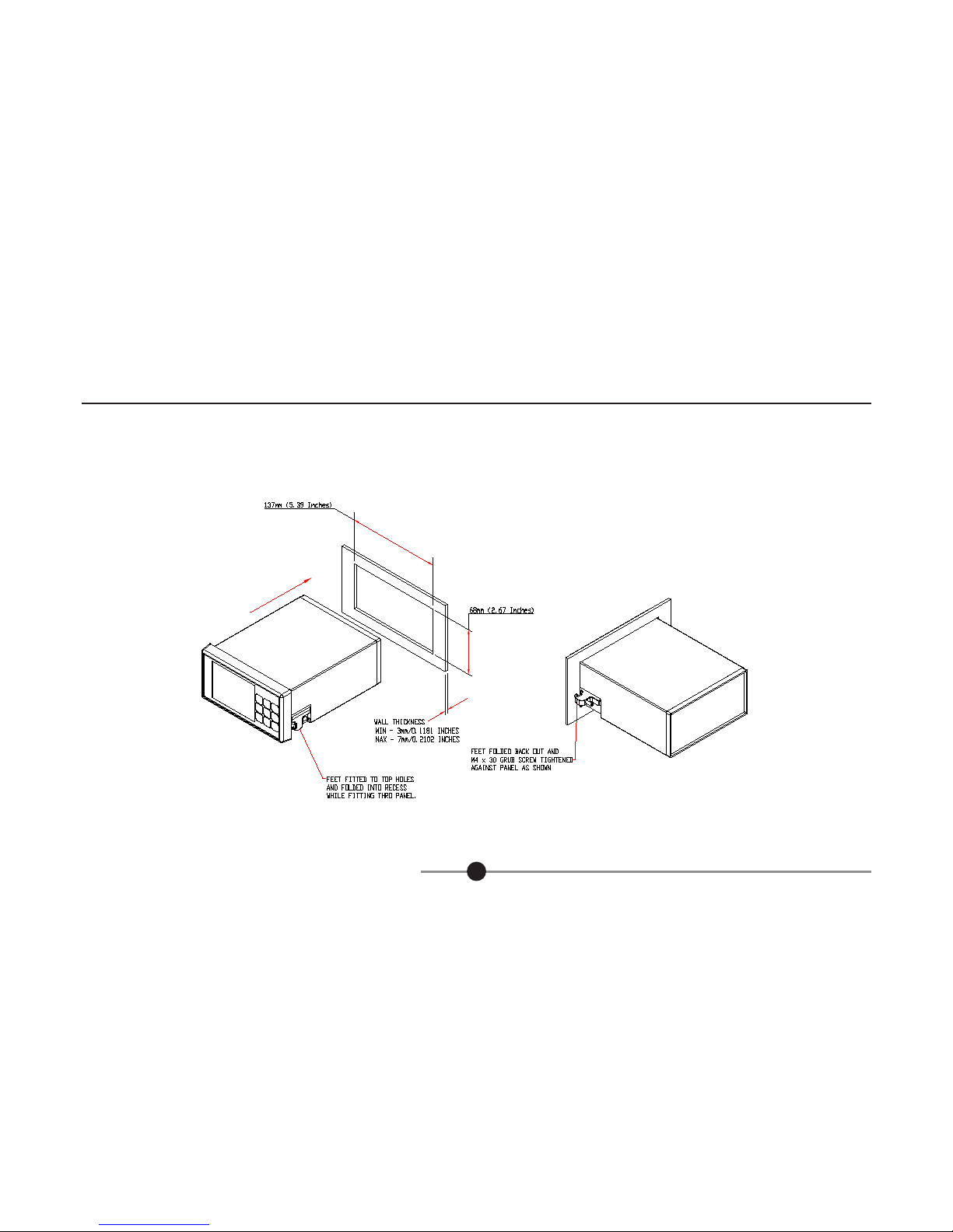
4.2 Panel Mounting
- Ensure that there is sufficient space behind the relevant instrument panel for the SI3300 and its cabling (refer to section 4.3 for dimensions).
- Cut out the panel aperture to the dimensions shown.
- Working from behind the panel, with the box fully located, fit the side brackets to the studs and slide them forward toward the panel until they lock into
place.
- Screw the brackets to the panel.
CAUTION: Do not over tighten the screws as this may damage the case of the instrument.
WARNING: On installing or removing the SI3300, you must be aware of any hazardous equipment or materials in the vicinity. Make sure that any
equipment into which the SI3300 system is to be installed is switched off and made safe.
CAUTION: Avoid installing the SI3300 close to switch gear, contactors or motor starters.
CAUTION: Do not place other signal and power supply wiring in the same loom as the SI3300 wiring.
CAUTION: Use screened cables for all leads, with the screen earthed at one end only.
4.0 Bench Mounted or Installed into a Panel (cont.) 6
502810 issue 6
4.0 Bench Mounted or Installed into a Panel (cont.)
4.3 Panel Dimensions
4.0 Bench Mounted or Installed into a Panel (cont.) 7

502810 issue 6
4.0 Bench Mounted or Installed into a Panel (cont.)
4.4 Assembly Dimensions
4.0 Bench Mounted or Installed into a Panel (cont.) 8

5.0 Display Panel
502810 issue 6
5.0 Display Panel
9
5.1 Layout of Front Panel
1 Liquid Crystal Operator Colour Display
2 Return to Setup Menu
3 Scroll Up (Moves cursor around screen), Apply Preset (ABS/PRE)
4 Print Option
5 Enter
6 Scroll Right (select option)
7 Track, Peak+, Peak-, Diff
8 Scroll Down (Moves cursor around screen)
9 Zero (ABS/TARE)
10 Scroll Left (select option)
Inhaltsverzeichnis
Andere Solarton Metrology Monitor Handbücher


