Sony Ericsson T100 Bedienungsanleitung

Working Instructions, SP/Mechanical
3_00021-1/FEA 209 544/78 C
Sony Ericsson Mobile Communications AB
Approved according to 000 21-LXE 107 42/1
Working Instructions, SP/Mechanical
Applicable for T100/T102/T105/T106
Contents:
1Disassembly .....................................................................................................................2
1.1 Process Tools.....................................................................................................2
1.2 Equipment..........................................................................................................2
1.3 Instructions ........................................................................................................2
2Reassembly ......................................................................................................................5
2.1 Process Tools.....................................................................................................5
2.2 Equipment..........................................................................................................5
2.3 Instructions ........................................................................................................5
3Replacement of Mechanical Parts .................................................................................8
3.1 Front Cover........................................................................................................8
3.2 Microphone......................................................................................................10
3.3 Battery connectors ...........................................................................................11
3.4 Speaker ............................................................................................................12
3.5 Keypad.............................................................................................................13
3.6 Display assembly.............................................................................................14
3.7 Buzzer protection rubber .................................................................................17
3.8 Volume key .....................................................................................................18
3.9 Vibrator Assembly...........................................................................................19
3.10 Antenna Cover Replacement...........................................................................20
4Process Tools for Label ................................................................................................22
4.1 Instructions ......................................................................................................22
5Revision History............................................................................................................23

Working Instructions, SP/Mechanical
3_00021-1/FEA 209 544/78 C
Sony Ericsson Mobile Communications AB
2(23)
1 Disassembly
1.1 Process Tools
• Torque screwdriver, torx no.6 set to 15 Ncm.
• Pair of tweezers
• Top opening tool NTZ 112 302
• Antenna cover opener NTZ 112 504
1.2 Equipment
• ESD-gloves (cotton gloves)
• ESD-wristband
1.3 Instructions
# Figure Instruction Note
1
Fig. 1.1
Release the battery and
remove it. (Fig. 1.1)
2
Fig. 1.2
Use the antenna cover
opener NTZ 112 504 to
remove the antenna
cover. (Fig. 1.2) Place it
under the snap hooks.
Be careful so you don’t
scratch the antenna cover
or the rear cover.

Working Instructions, SP/Mechanical
3_00021-1/FEA 209 544/78 C
Sony Ericsson Mobile Communications AB
3(23)
# Figure Instruction Note
3
Fig. 1.3
Press down the tool until
the antenna cover
releases from the rear
cover. (Fig. 1.3)
You may need to use
some force. The tips at the
Antenna opening tool
must be pushed as far as
possible between the
antenna cover and the rear
cover.
4
Fig. 1.4
Remove the 4 screws.
(Fig. 1.4)
5
Fig. 1.5
Use the Top opening
tool to release the Rear
cover from the Front
cover. Place the tool
between the Rear cover
and the Front cover.
(Fig. 1.5)
Place the Top opening
tool as shown at the
picture.
Do not use a screwdriver
or other sharp tools; it
might cause some damage
to the plastics or other
components.
6
Fig. 1.6
Remove the volume key
with help of a pair of
tweezers. (Fig. 1.6)
Release the Volume key
from the front cover, by
lifting if straight up.

Working Instructions, SP/Mechanical
3_00021-1/FEA 209 544/78 C
Sony Ericsson Mobile Communications AB
4(23)
# Figure Instruction Note
7
Fig. 1.7
There are 3 hooks
holding the PCB into the
front cover. 2 in the top
and 1 in the lower left
corner. (Fig. 1.7)
8
Fig. 1.8
Use a Top opening tool
to release the lower left
hook.
(Fig. 1.8 & Fig. 19)
Note! There is a risk of
damaging the PCB or the
front cover if you are not
using the Top opening
tool.
9
Fig. 1.9
When Top opening tool
is placed in the right
position (as in the
picture) Release the
PCB from the front
cover hook by pushing
the Top opening tool
downwards.
10
Fig. 2.0
Lift the PCB up by grab
hold of the system
connector with your
fingers.
(Fig. 2.0)
Working Instructions, SP/Mechanical
3_00021-1/FEA 209 544/78 C
Sony Ericsson Mobile Communications AB
5(23)
2 Reassembly
2.1 Process Tools
• Torque screwdriver, torx no.6 set to 15 Ncm.
• Pair of tweezers
2.2 Equipment
• ESD-gloves (cotton gloves)
• ESD-wristband
2.3 Instructions
# Figure Instruction Note
1
Fig. 2.1
Place the PCB under the 2
hooks in the top. (Fig. 2.1)
2
Fig. 2.2
Press on the system
connector to make the
PCB fit tightly to the front
cover. (Fig. 2.2)
3
Fig. 2.3
Mount the volume key
with a pair of tweezers.
(Fig. 2.3 & Fig. 2.4)
Position the volume key as
shown on the pictures.

Working Instructions, SP/Mechanical
3_00021-1/FEA 209 544/78 C
Sony Ericsson Mobile Communications AB
6(23)
# Figure Instruction Note
4
Fig. 2.4
Make sure that the hole on
the volume key is position
according to the volume
switch on the PCB.
5
Fig. 2.5
Mount Rear Cover into the
Front cover. Start with the
top and press on each side
of it with your fingers to it
fit tightly. (Fig. 2.5)
Arrows indicate where to
press.
6
Fig. 2.6
Tighten the 4 screws.
(Fig. 2.6)
Use a torque screwdriver
torx no. 6 set to 15 Ncm.

Working Instructions, SP/Mechanical
3_00021-1/FEA 209 544/78 C
Sony Ericsson Mobile Communications AB
7(23)
# Figure Instruction Note
7
Fig. 2.7
Mount the antenna into the
rear cover. Start with the
top (1) simultaneously
press down the 2 snap
hooks (2 & 3)
(Fig. 2.7)

Working Instructions, SP/Mechanical
3_00021-1/FEA 209 544/78 C
Sony Ericsson Mobile Communications AB
8(23)
3 Replacement of Mechanical Parts
3.1 Front Cover
3.1.1 Process Tools
• Pair of tweezers
3.1.2 Equipment
• ESD-gloves (cotton gloves)
• ESD-wristband
3.1.3 Instructions
• Disassemble the phone as described in 1 Disassembly (page 2-4), follow steps 1-10
# Figure Instruction Note
1
Fig. 3.1.1
Remove the keypad, with
a pair of tweezers.
(Fig. 3.1.1)
Do not touch the dome.
2
Fig. 3.1.2
Remove the speaker with
a pair of tweezers.
(Fig. 3.1.2)
Never reuse removed
speaker due to conductivity
problems.
3
Fig. 3.1.3
Press the tips of the
tweezers in the slit, on
each side of the speaker,
and then lift. (Fig. 3.1.3)
Do not lift in the
connectors they are easy to
damage.

Working Instructions, SP/Mechanical
3_00021-1/FEA 209 544/78 C
Sony Ericsson Mobile Communications AB
9(23)
# Figure Instruction Note
4
Fig. 3.1.4
To remove the
microphone. Press the
microphone upwards from
the front cover with help
of a pair of tweezers. Press
on the rubber sides until
the microphone is released
from the cavity.
(Fig. 3.1.4)
5
Fig. 3.1.5
Take a new front cover
and place the keypad
inside the front cover with
the help of a pair of
tweezers. (Fig. 3.1.5)
Do not touch the dome.
6
Fig. 3.1.6
Pick up the microphone
with the help of a pair of
tweezers and place it in
the front. (Fig. 3.1.6)
Press on the microphone
until it reaches the bottom
of the cavity. Use gloves
so you don’t contaminate
the elastomer.
7
Remove the foil from the
speaker and place it with
the contacts facing
upwards.
8
Remove the protection
gasket inside the window.
Be careful not to scratch
the inside of the front
window with the pair of
tweezers.
• Assemble the phone as described in 2 Reassembly (page 5-6), follow steps 1-7

Working Instructions, SP/Mechanical
3_00021-1/FEA 209 544/78 C
Sony Ericsson Mobile Communications AB
10(23)
3.2 Microphone
3.2.1 Process Tools
• Pair of tweezers
3.2.2 Equipment
• ESD-gloves (cotton gloves)
• ESD-wristband
3.2.3 Instructions
• Disassemble the phone as described in 1 Disassembly (page 2-4), follow steps 1-10
# Figure Instruction Note
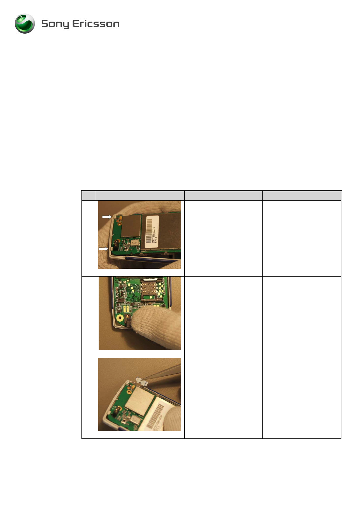
1
Fig. 3.2.1
Remove the microphone
from the cavity on the
front cover with a pair of
tweezers. (Fig. 3.2.1.)
2
Pick up the new
microphone with a pair
of tweezers.
3
Fig. 3.2.2
Mount the microphone
in the cavity in the front
cover. Press the
microphone to it reach
the bottom of the cavity.
(Fig. 3.2.2)
Use gloves, if the
elastomer will be
contaminated, it can result
in connection problems.
• Assemble the phone as described in 2 Reassembly (page 5-6), follow steps 1-7
Andere Handbücher für T100
4
Dieses Handbuch passt für folgende Modelle
3
Inhaltsverzeichnis
Andere Sony Ericsson Telefon Handbücher

Sony Ericsson
Sony Ericsson K330 Bedienungsanleitung

Sony Ericsson
Sony Ericsson HCB-108 Bedienungsanleitung

Sony Ericsson
Sony Ericsson 1130601 Bedienungsanleitung

Sony Ericsson
Sony Ericsson K850 Bedienungsanleitung

Sony Ericsson
Sony Ericsson HCB-120 Bedienungsanleitung

Sony Ericsson
Sony Ericsson W902 Walkman Bedienungsanleitung

Sony Ericsson
Sony Ericsson Z250 Bedienungsanleitung

Sony Ericsson
Sony Ericsson Walkman W580i Bedienungsanleitung

Sony Ericsson
Sony Ericsson K660i Bedienungsanleitung

Sony Ericsson
Sony Ericsson GR47/GR48 Bedienungsanleitung


