sparkfun XBee Shield Technisches Dokument

XBee Shield Hookup Guide
Introduction
Heads up! Originally, this tutorial was written to configure an XBee Series 1 to communicate in transparency
mode. However, this can apply to the XBee Series 3 module as long as you configure the firmware to the
legacy 802.15.4 protocol. For more information, check out the Exploring XBees and XCTU tutorial.
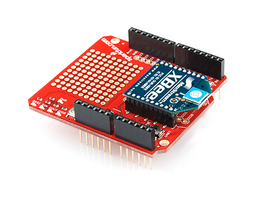
The XBee Shield gives your Arduino a seamless interface to XBee -- one of the most popular wireless platforms
around. With XBee, instead of being tied down by a serial cable -- inches away from a paired device -- your
Arduino can pass data over the air to another device hundreds of feet away.
SparkFun XBee Shield
WRL-12847

Part of what makes XBee so popular is its simplicity. XBees are controlled over a serial UART interface -- in the
most basic operation they can be used as a wireless serial cable. Setting up XBee networks and addresses is
also simplified with Digi's free software -- XCTU -- which we explain in a separate tutorial.
Covered In This Tutorial
The goal of this tutorial is to set up wireless XBee communication between a computer and an Arduino/XBee
Shield combo. Then, using a terminal program, we can remotely send data to an Arduino, or read data off of it.
SparkFun XBee 3 Wireless Kit
KIT-15936
Product Showcase: SparkFun XBee 3 Wireless KitProduct Showcase: SparkFun XBee 3 Wireless Kit

We'll begin by examining the schematics and hardware of the XBee Shield, then move on to example code. First
we'll set up a test program to make sure our XBees are communicating with each other. Then we'll move on to the
remote control Arduino sketch.
Required Materials
To follow along with this tutorial, you will need the following materials. You may not need everything though
depending on what you have. Add it to your cart, read through the guide, and adjust the cart as necessary.
1x XBee Shield -- The star of this tutorial.
You'll also need headers to install into your shield. We recommend stackable headers.
1x Arduino -- The XBee Shield should work with any Arduino-compatible board -- Uno, RedBoard, Mega,
you name it.
2x XBees -- XBees exist in a variety of series, frequencies, and ranges. If you're just getting started with
XBee, we highly recommend going with Series 1 models -- either with a trace antenna, wire antenna or u.fl
connector.
For more help picking an XBee, check out our XBee Buying Guide.
Heads up! While this tutorial was written for XBee Series 1, you can still follow along using XBee
Series 3 modules. Just make sure to configure it with the 802.15.4 (Series 1) firmware. For more
information, check out the Exploring XBees and XCTU tutorial.
1x Explorer -- The Explorer board allows you to connect an XBee to your computer. You can use either the
Explorer USB, Explorer USB Dongle, or Explorer Serial.
Depending on which explorer you have, you may also need a matching mini-B USB or serial cables.
At least one computer with X-CTU installed.
The latest version of X-CTU is available for both Mac and Windows!
Tools
You will need a soldering iron, solder, and general soldering accessories.
Solder Lead Free - 100-gram Spool
TOL-09325
Weller WLC100 Soldering Station
TOL-14228

Suggested Reading
Before reading through this tutorial, we highly recommend checking out the Exploring XBees and XCTU tutorial.
That tutorial will introduce you to XCTU and explain how to configure XBee networks and addresses. In addition to
that tutorial, we also recommend checking these guides out:
Serial Communication -- Serial communication is critical to controlling and managing XBees.
Arduino Shields -- The basics of Arduino Shields, including how to assemble a shield.
XBee Buying Guide -- We highly recommend Series 1 XBee's, if this is your first time playing with them. If
you're curious about other XBee classes, check out this guide!
Exploring XBees and XCTU
MARCH 12, 2015
How to set up an XBee using your computer, the X-CTU software, and an XBee
Explorer interface board.
How to Solder: Through-Hole Soldering
This tutorial covers everything you need to know about
through-hole soldering.
Serial Communication
Asynchronous serial communication concepts: packets,
signal levels, baud rates, UARTs and more!

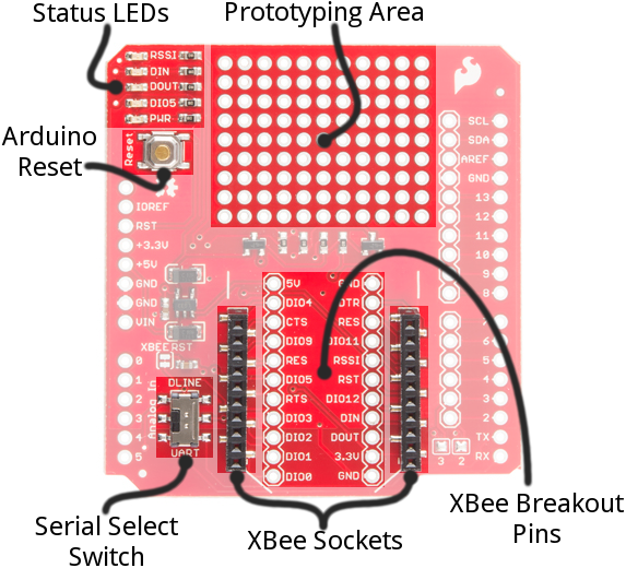
Hardware Overview
Here's a quick overview of the most components of the XBee Shield:
Below we'll go more in-depth on the most important components of the shield.
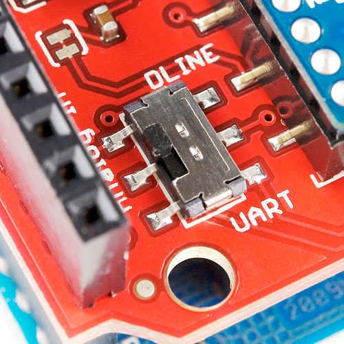
UART/Software Serial Switch
One of the most important components on the XBee Shield is the DLINE/UART switch. This switch controls which
Arduino pins interface with the XBee.
Arduino Shields
All things Arduino Shields. What they are and how to
assemble them.

The Arduino Uno has a single hardware UART, which is usually either used for programming (via the Arduino's
serial bootloader) or communication with the serial monitor. That serial port can only be used to communicate
with one device at any time, lest you run into problems of bus contention. There's also a chance that, during
program upload, spurious -- even harmful -- data might be sent to any device attached to the Arduino's hardware
UART.
So to avoid any problems that might arise from connecting the XBee to the Arduino's hardware UART, we usually
take advantage of the Software Serial library, connecting the XBee's RX and TX pins to a pair of free digital pins
on the Arduino.
To select between software and hardware serial, the XBee Shield includes a small, surface-mount slide switch.
This switch allows you to select between the hardware serial port (UART position) and a software serial port
connected to pins 2 (Arduino-side RX) and 3 (Arduino-side TX).
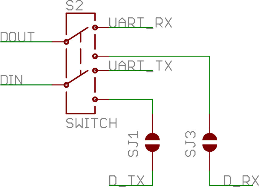
The switch configuration from the XBee Shield schematic. "D_TX" connects to Arduino pin 3, and "D_RX"
connects to Arduino pin 2.
For all of our example sketches we'll assume the switch is in the DLINE position. At the very least, make sure
the switch is in the "DLINE" position when uploading sketches.
Status LED Indicators
There are 5 LEDs on the XBee Shield. Each of these LEDs connects to a pin on the XBee, which does most of the
LED driving. Here's a table explaining the operation of each LED:

LED
Label
LED
Color
XBee Pin
Connection
Default Operation Notes
PWR Red 3.3V Indicates power is present.
DIO5 Green Associate/DIO5 Associated indicator -- blinks when the XBee is associated with
another XBee.
DOUT Red DOUT Indicates wireless data is being received.
DIN Green DIN Indicates wireless data is being transmitted.
RSSI Green PWM0/RSSI Indicates relative signal strength (RSSI) of last received
transmission.
These LEDs can be very useful for debugging. The DIO5/Associate indicator should blink when the XBee is paired
with a compatible device. The RSSI LED is actually PWM'd so it will be brighter when the paired XBee is closer
(sending a stronger signal).
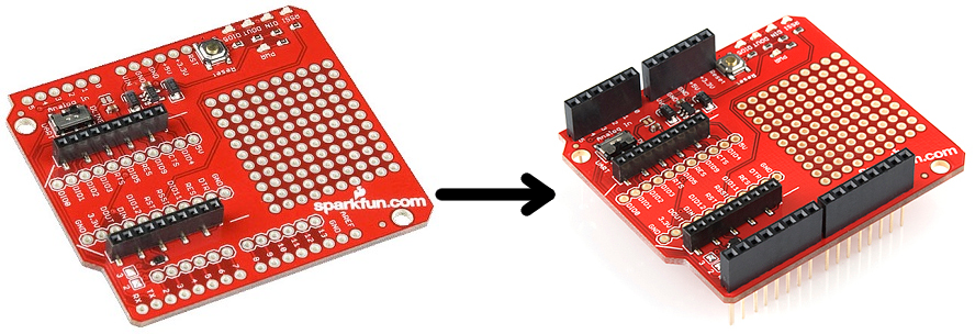
Assembly Tips
Before you can use the XBee Shield with your Arduino, you'll need to solder in some headers.
Check out the assembly page of our Shield tutorial for all of the tips and tricks related to header installation.
Arduino Shields
AUGUST 6, 2013
All things Arduino Shields. What they are and how to assemble them.

XBee Socket
There is some white silkscreen on the Shield PCB to help orient your XBee as you're plugging it in. Make sure to
match up the XBee's two diagonal edges with the two diagonal lines on the PCB.
With everything installed, you're ready for the next step! Time to code...
Example: Communication Test
Note: This example assumes you are using the latest version of the Arduino IDE on your desktop. If this is
your first time using Arduino, please review our tutorial on installing the Arduino IDE.
Double-Check Your XBee Network
Heads up! Make sure that the XBees are configured correctly to communicate with each other in the
network.
Before continuing with this example, you'll need to make sure your XBee's are configured correctly -- they need to
be on the same network and have compatible destination and MY addresses. By default, XBees will all be
compatibly configured, but we recommend setting up unique network ID's and addresses. Check out the
Configuring Networks page of our Exploring XBee's and XCTU tutorial for help with that.

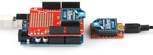
This example assumes you have XCTU installed and two compatibly-configured XBees -- one connected to your
computer via a USB Explorer (or Dongle, or Serial Explorer) and another plugged into the Shield/Arduino.
The Arduino Sketch
Let's start simple. In this section, we'll upload a sketch which passes data between your serial monitor and the
XBe using the serial UART. This sketch can be use to create a "portal of communication" between your Arduino's
serial monitor, and another XBee (connected to a computer via a USB Explorer). The first uses software serial
defined pins on an Arduino. The second example uses the native hardware serial defined pins.
Software Serial Passthrough
Here's the sketch we'll use. It makes use of the SoftwareSerial library, which is included with all of the recent
Arduino releases. Before uploading this sketch, make sure the switch on the Shield is in the "DLINE" position!
Copy and upload the sketch below.
Exploring XBees and XCTU
MARCH 12, 2015
How to set up an XBee using your computer, the X-CTU software, and an XBee
Explorer interface board.

/*****************************************************************
XBee_Serial_Passthrough.ino
Set up a software serial port to pass data between an XBee Shield
and the serial monitor.
Hardware Hookup:
The XBee Shield makes all of the connections you'll need
between Arduino and XBee. If you have the shield make
sure the SWITCH IS IN THE "DLINE" POSITION. That will connect
the XBee's DOUT and DIN pins to Arduino pins 2 and 3.
*****************************************************************/
// We'll use SoftwareSerial to communicate with the XBee:
#include <SoftwareSerial.h>
//For Atmega328P's
// XBee's DOUT (TX) is connected to pin 2 (Arduino's Software RX)
// XBee's DIN (RX) is connected to pin 3 (Arduino's Software TX)
SoftwareSerial XBee(2, 3); // RX, TX
//For Atmega2560, ATmega32U4, etc.
// XBee's DOUT (TX) is connected to pin 10 (Arduino's Software RX)
// XBee's DIN (RX) is connected to pin 11 (Arduino's Software TX)
//SoftwareSerial XBee(10, 11); // RX, TX
void setup()
{
// Set up both ports at 9600 baud. This value is most important
// for the XBee. Make sure the baud rate matches the config
// setting of your XBee.
XBee.begin(9600);
Serial.begin(9600);
}
void loop()
{
if (Serial.available())
{ // If data comes in from serial monitor, send it out to XBee
XBee.write(Serial.read());
}
if (XBee.available())
{ // If data comes in from XBee, send it out to serial monitor
Serial.write(XBee.read());
}
}
Software Serial Note
The demo code was originally designed for the ATmega328P on the Arduino Uno. Not all the pins can
support change interrupts for a serial Rx pin depending on what Arduino microcontroller is used. If you were
using it with ATmega2560 (i.e. Arduino Mega 2560) or ATmega32U4 (i.e. Arduino Leonardo, Pro Micro
Andere Handbücher für XBee Shield
1
Dieses Handbuch passt für folgende Modelle
1
Inhaltsverzeichnis
Andere sparkfun Controller Handbücher


