sparkfun Raspberry Pi Zero Wireless Camera Kit Gebrauchsanweisung


Required Materials
You'll need a microSD card, a sufficient power supply, and a micro-B USB Cable. We do not recommend the pre-
installed NOOBS card, as it may not include a recent enough version of the Pi operating system to support the Pi
Zero W.
Required Tools
You'll need a few tools to assemble this kit: just a standard soldering iron, solder, a small screwdriver, and a pair of
side cutters.
microSD Card with Adapter - 16GB (Class 10)
COM-13833
Wall Adapter Power Supply - 5.1V DC 2.5A
(USB Micro-B)
TOL-13831
USB micro-B Cable - 6 Foot
CAB-10215

Suggested Reading
Very little of this kit requires anything but following our step-by-step guide; however, you might want to check out
our through hole soldering tutorial as you'll need to do some soldering to put the pins in place on the Pi Zero W
and the Pi Servo Hat. Other, tutorials you might be interested in reading include:
Solder Lead Free - 15-gram Tube
TOL-09163
Soldering Iron - 30W (US, 110V)
TOL-09507
Flush Cutters - Xcelite
TOL-14782
Tool Kit - Screwdriver and Bit Set
TOL-10865
How to Solder: Through-Hole Soldering
This tutorial covers everything you need to know about
through-hole soldering.
Hobby Servo Tutorial
Servos are motors that allow you to accurately control
the rotation of the output shaft, opening up all kinds of
possibilities for robotics and other projects.

Prepare the MicroSD Card
To prepare the microSD card, we need to:
Download the latest Raspberry Pi Raspbian Jessie image.
Create an microSD card that contains this boot image.
Edit the "config.txt" file on the microSD card to enable the serial debug console.
Create a "wpa_supplicant.conf" file on the SD card to enable WiFi.
Let's walk through these steps in more detail!
Download the Latest Raspbian Jessie Image
You can find the image on the Raspberry Pi Foundation Website. It's a fairly large download so go get a snack or
play a game or something.
Note: Make sure that you don't download "RASPBIAN XYZ LITE", as the Lite installation is lacking several
utilities and programs we'll need to get things moving. Note that XYZ is a placeholder for the release name of
the distribution; at the time of this writing, that name is "Stretch".
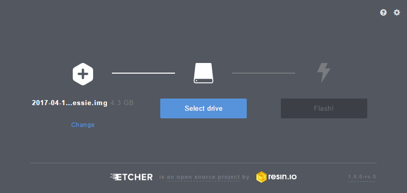
Burn the Image to an MicroSD Card
To write the image to the card, there exists an excellent utility for Mac/Linux/Windows called Etcher. Simply
download and install it to your computer. Then select the image you downloaded earlier, the drive you want to
install to (Etcher won't let you install to anything but a removable drive, and if only one drive is available, it will
select it automatically!), and click "Flash!"
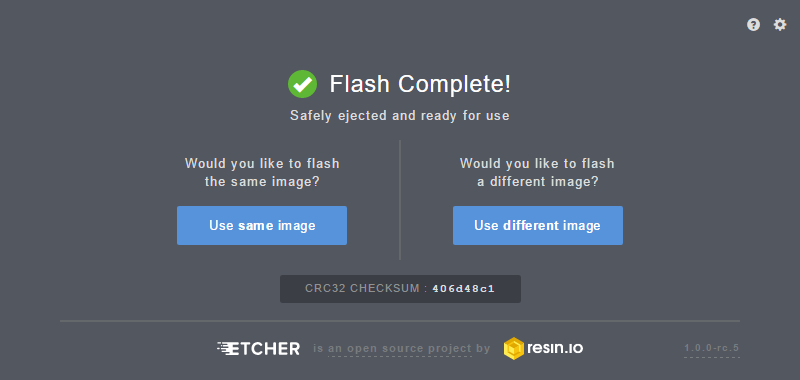
This is another long-ish process, requiring several minutes to complete. Once complete, the window will display a
"Flash Complete!" message.
Pi Servo Hat Hookup Guide
This hookup guide will show you how to connect and
use the Pi Servo Hat in a project.
Getting Started with the Raspberry Pi Zero
Wireless
Learn how to setup, configure and use the smallest
Raspberry Pi yet, the Raspberry Pi Zero - Wireless.

By default, Etcher "ejects" the card after it has created the image, so you'll need to pull it out and reinsert it to get
your computer to reload the disk.
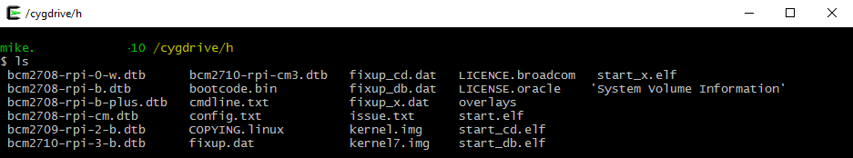
Edit the "config.txt" File on the MicroSD Card
To continue, we're going to need to edit a file on the microSD card. This file will be visible from any operating
system, although on a Linux system it's in a slightly different location.
On a Windows or Macintosh, the files will be loaded in the root directory of the microSD card, so when you open a
window of the drive, you'll see them directly. In Linux, the card will be mounted, and you'll have to navigate to the
"Boot" directory on the card to find the file we're looking for.
Here's a list of all the files in the directory of interest.
Click the image for a closer look.
Open the file "config.txt" in your favorite text editor (i.e. Notepad++, TextWrangler, ConTEXT Editor, etc.) and add
this line to the very end:
enable_uart=1
Note: Despite the presence of a hash ('#') in front of the other lines in this file, you must not put one in front
of this line. That would comment it out, causing it to be ignored. Adding this line will enable the UART on the
GPIO pins so you can complete the rest of the process without having to hook your Pi Zero W up to a monitor
and keyboard. Pretty nifty!
Create a "wpa_supplicant.conf" File on the MicroSD Card to Enable WiFi
Troubleshooting Tip: For users having difficulty enabling WiFi on Pi Zero in this step, you could use the
PIXEL desktop GUI if you access to a monitor and mini-HDMI adapter to connect to your network. You can
also enable the camera, I2C, and SSH through Preferences > Raspberry Pi Configuration from the
desktop menu.

The last thing we need to do to prepare the microSD card is to create a "wpa_supplicant.conf" file on the card.
This file contains the information needed for your local wireless network setup.
Create a new file using your favorite text editor. On Windows we recommend Notepad, as it provides WYSIWYG
content and allows you to save a file with an arbitrary file extension. On MacOS, TextWrangler seems to be the
easiest. For Linux, your default system text editor should be fine.
The contents of the file can be quite simple. Most likely, you can get away with something that looks like this:
network={
ssid="YOUR_SSID"
psk="YOUR_PASSWORD"
key_mgmt=WPA-PSK
}
Once added, modify the network ID and password for your WiFi network. Then save the file as
"wpa_supplicant.conf" to the microSD card.
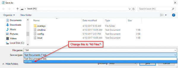
Important Note: On the on the "Save As..." screen for Windows users, you'll need to change the file
extension type under the field "Save as type:" from "*.txt file" to "All files". Then you will need to explicitly
name the file "wpa_supplicant.conf", or Notepad will automatically append ".txt" to the file name, breaking
this functionality. See the image below.
Click the image for a closer look.
Some variation of this "Save as..." and removing the appended ".txt" suffix is necessary in Mac OS and Linux
as well, but should be equally simple.
Pull the MicroSD Card and Insert It into the Pi Zero W
This is all we need to do in preparation of our first boot. You can now remove the card from your computer and put
it into the Pi Zero W. Don't power it up yet, though!

Hardware Assembly
To assemble the hardware, we need to:
Solder headers to the Raspberry Pi Zero W.
Solder headers to the Pi Servo Hat.
Install the Pi Servo Hat on the Pi Zero W.
Assemble the pan-tilt hardware and connect the servos to the hat.
Let's walk through these steps in more detail!
Solder Headers to the Raspberry Pi Zero W and the Pi Servo Hat
We recommend soldering the male header to the Pi Zero W and the female to the Pi Servo Hat. If you have any
issues with soldering, please check out our learn to solder tutorial.
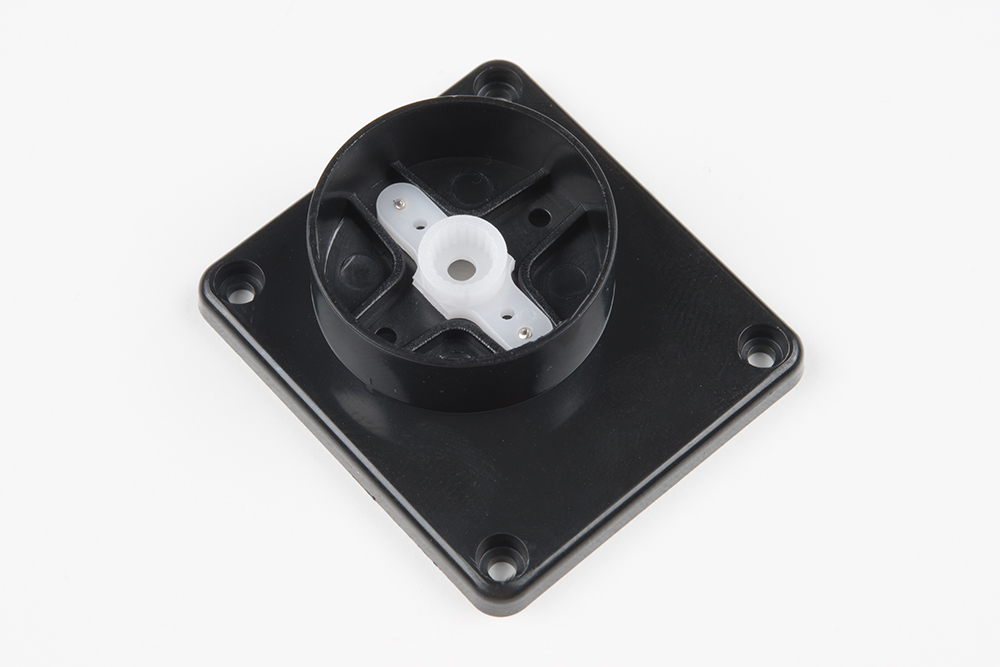
Assemble the Pan-Tilt Mechanism
Assembly of the pan-tilt mechanism is fairly straightforward. The trickiest part is making sure the servo motors are
centered during assembly.
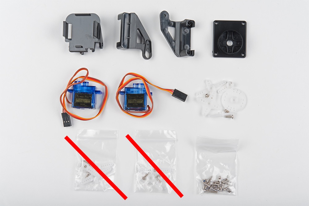
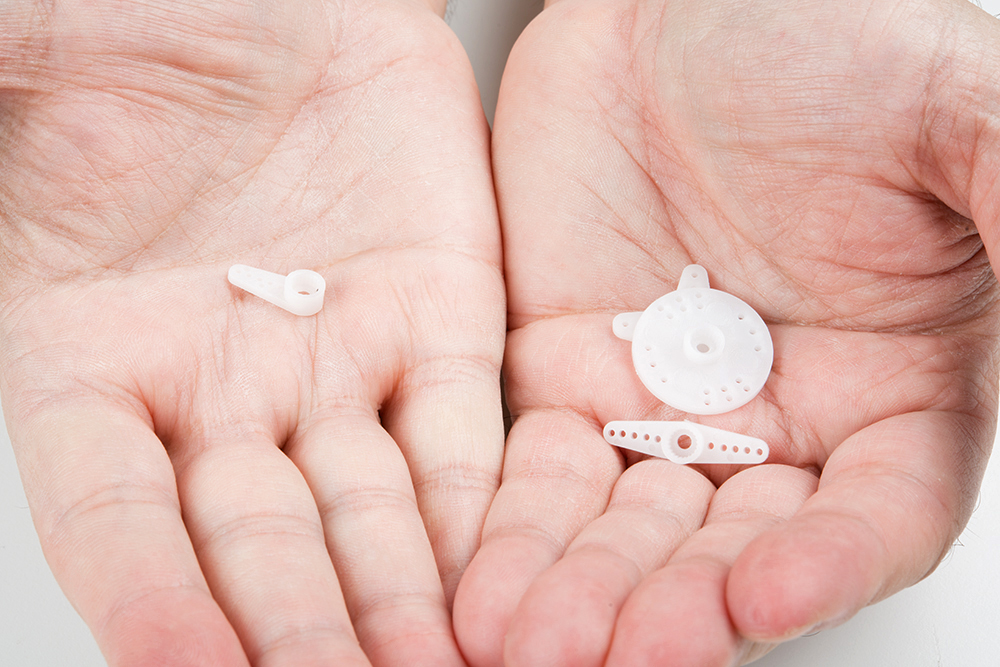
Here's the family portrait of the stuff that comes in the kit. You won't be needing the servo horns that come
packaged with the servo motors, just the ones that come packaged separately.
Heads up! The servo hardware may vary depending on the supplier. You may need to clip the arm servo
horn with 6 holes and use the screws that were packaged separately.
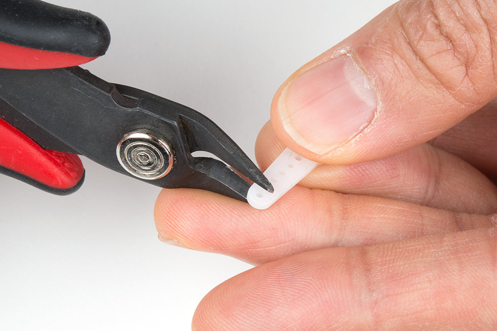
Start by identifying the servo horn with two long arms and two short arms. You'll need to clip off the long arms, as
shown below.

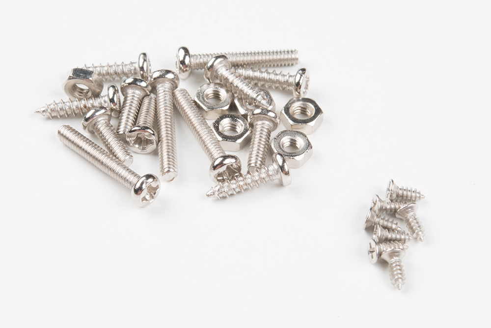
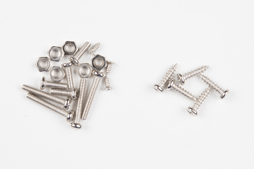
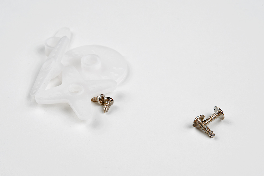
Identify the smallest screws in the baggie of screws that came with the kit. These will be used to affix this horn to
the base of the pan-tilt mechanism.
Place the horn in the base as shown, then screw it down by inserting the screws from the bottom and threading
them into the horn. Note that there will be extra screws, even beyond the ones to be used later. This is generally
true of all the screws in this set.
Next, identify the larger self-tapping screws. These will be used for assembling the next part of the mechanism.
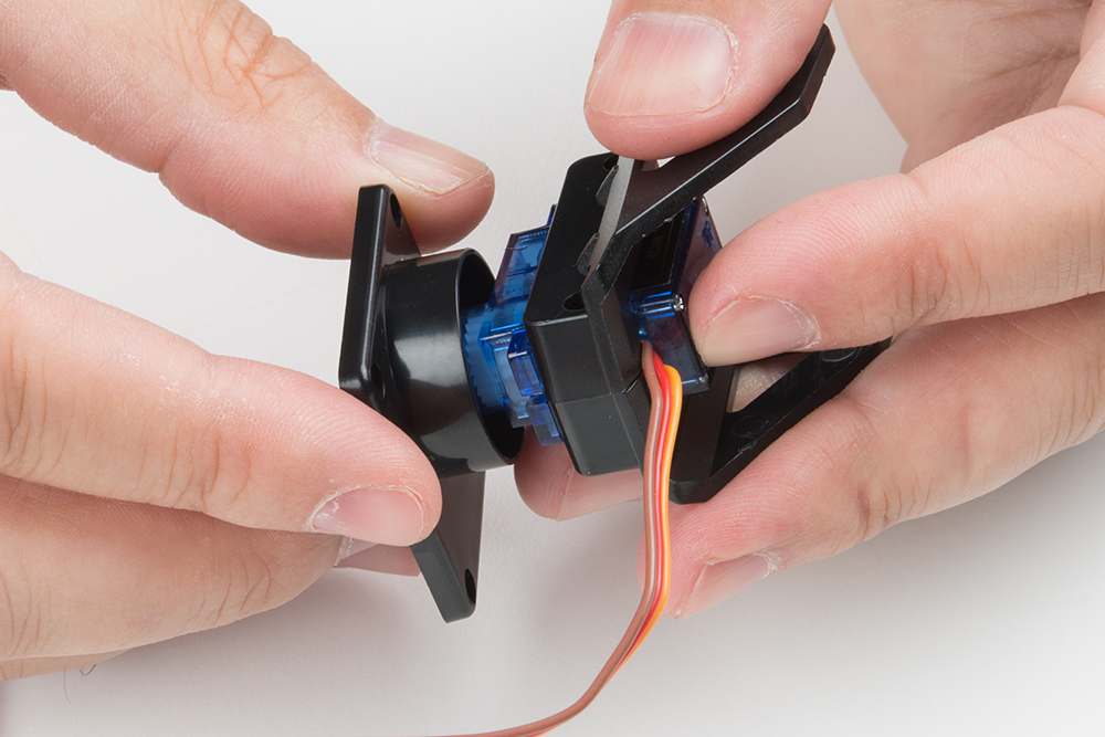
Find the two pieces pictured below that will sandwich the first servo. Note the orientation of the servo in these
pieces.

Here's the sandwiched servo. Again, note the orientation for proper assembly.
Here, you can see where the screws identified a couple of steps ago fit into our servo sandwich. Tighten them
down, but not too much.
Now fit the shaft of the servo into the fitting on the horn that you previously installed into the base. This is the point
where you need to make sure that the shaft is roughly centered in order for the entire assembly to work properly. I
do this by turning the shaft all the way to one extreme, then turning it 90 degrees back in the other direction. Then,
I remove the base and line it up with the body of the servo motor.

Find the two longer screws that came with the horn kit in the set to attach the base to the servo. There will likely be
only two of these, and you need both, so don't lose one! Insert the screw to the bottom and tighten the screw to
attach the two parts together.
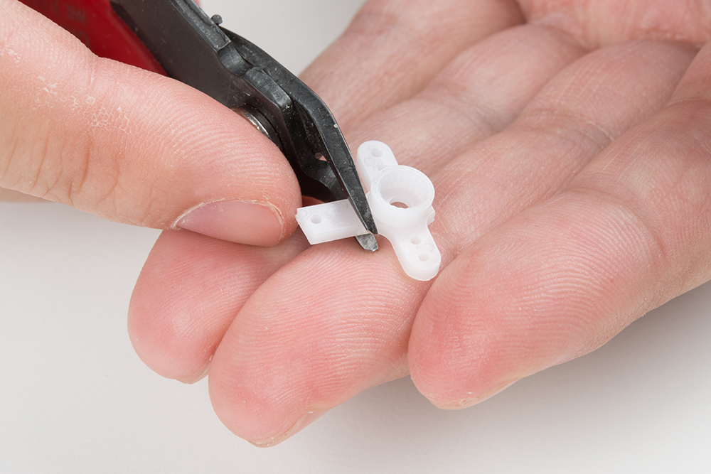
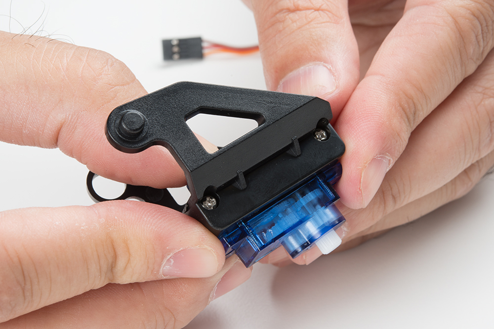
You'll now need the single arm servo horn with 5 holes, as shown in the image below on the left. If the single arm
servo with 5 holes was not included in the kit, you will need to modify one of the servo horn with 6 holes that was
packaged separately. Shorten the horn by clipping off one hole as shown in the image below on the right and
checking to see if it fits the mold on the tilt bracket. Be careful when clipping and make sure that you do not clip off
too much of the horn.
Single arm servo horn with 5 holes. Single arm servo horn with 6 holes being clipped.
Install the single arm servo horn as shown below. You'll need two of the small self-tapping screws from the first
step to affix it to the mechanism.
Dieses Handbuch passt für folgende Modelle
1
Inhaltsverzeichnis
Andere sparkfun Digitalkamera Handbücher


