
Spyder 2021 ALLEGRO RED Bedienungsanleitung

1/16
7in LCD Screen
Guide
2021 ALLEGRO RED/BREEZE

2/16
USER GUIDE –7in LCD SCREEN
Contents
HOME PAGE ..........................................................................................................................................4
Figure 1 (Lighting Section)....................................................................................................................4
Figure 2 (Climate Section)....................................................................................................................4
Figure 3 (Water Heat)..........................................................................................................................4
Figure 4 (Power Section)......................................................................................................................4
Figure 5 (Tank Section) ........................................................................................................................4
2. Lights Page.......................................................................................................................................5
3. Climate Page....................................................................................................................................5
4. Fans/Mechanical Page .....................................................................................................................5
5. Slides Page.......................................................................................................................................5
6. Settings Page ..................................................................................................................................5
1. Page Designation .............................................................................................................................5
2. Active Fault Icon ..............................................................................................................................5
3. Home Icon .......................................................................................................................................5
LIGHTING PAGE .......................................................................................................................................6
Figure 1 (Main) ....................................................................................................................................6
Figure 2 (Light Master).........................................................................................................................6
Figure 3 (Exterior)................................................................................................................................6
Figure 4 (Bed/Bath Lights) ...................................................................................................................6
CLIMATE PAGE ........................................................................................................................................7
Figure 1 (Zone + Ambient Temperature) ..............................................................................................7
Figure 2 (HVAC Mode Select)...............................................................................................................7
Figure 3 (HVAC Status).........................................................................................................................7
Figure 4 (Fan Control)..........................................................................................................................8

3/16
Figure 5 (Temperature Set Point).........................................................................................................8
SLIDE PAGE..............................................................................................................................................9
Figure 1 (Slide Extend/Retract) ............................................................................................................9
Figure 2 (Slide Run Warning)................................................................................................................9
Figure 3 (Slide Run Requirements Status).............................................................................................9
MECHANICAL PAGE ...............................................................................................................................10
Figure 1 (Fan On / Off) .......................................................................................................................10
Figure 2 (Ceiling Fan Control).............................................................................................................10
Figure 3 (Galley Shade Control).......................................................................................................... 10
Figure 4 (Fan Lid Up / Down)..............................................................................................................10
Figure 5 (Fan Location) ......................................................................................................................10
FAULT PAGE .......................................................................................................................................... 11
Figure 1 (Active Fault List)..................................................................................................................11
Figure 2 (Diagnostic Page Select) .......................................................................................................11
Figure 3 (Fault Warning) .................................................................................................................... 11
SETTINGS PAGE .....................................................................................................................................12
Figure 1 (Temperature Unit Toggle)...................................................................................................12
Figure 2 (Screen Brightness Adjust)....................................................................................................12
Figure 3 (Diagnostics) ........................................................................................................................12
Figure 4 (GUI Version)........................................................................................................................12
Figure 5 (Wireless Settings)................................................................................................................12
Figure 6 (Screen Settings) ..................................................................................................................12
Figure 7 (Coach Model Select) ........................................................................................................... 12
GLOSSARY ............................................................................................................................................. 13
General function of screen buttons and indicators............................................................................. 13
HOW TO REMOVE A NETWORK CABLE...............................................................................................13
DIAGNOSTIC LED FEATURES...................................................................................................................14
NET LED Functions.............................................................................................................................14
G6 + RSI-9 Location................................................................................................................................15
SUPPORT...............................................................................................................................................16
4/16
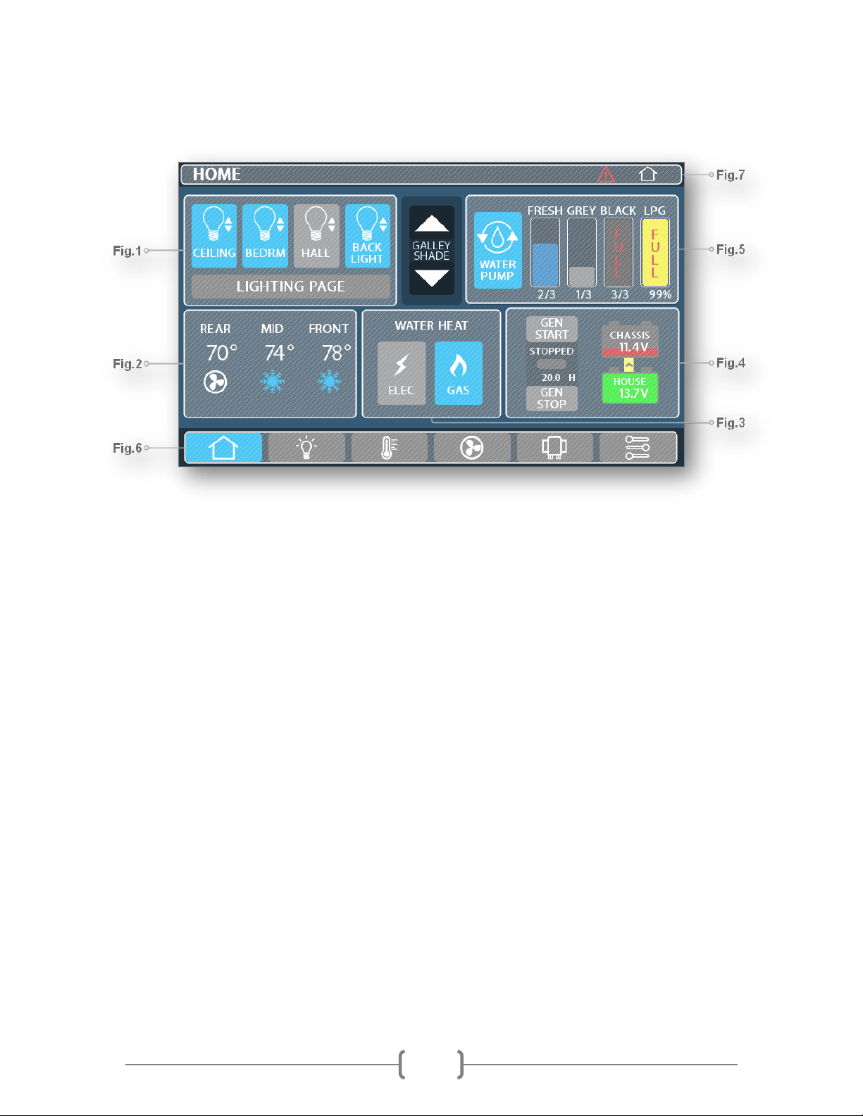
HOME PAGE
Figure 1 (Lighting Section)
▪This section allows you to have quick control over frequently used lights in the coach.
Figure 2 (Climate Section)
▪This section displays climate information and current heating, cooling, and fan status. Press on this
box to quickly jump to the climate page.
Figure 3 (Water Heat)
▪This button allows control over the heating mode for the water heater. Electric, gas or both can be
selected to heat the water system.
▪The gas will flash if the burner has failed to ignite. Tap the button off then back on to try
again. If the burner still does not ignite contact the water heater manufacture for support.
Figure 4 (Power Section)
▪This section displays power information for the coach. This includes house and chassis battery
status, merge status. To turn on the generator press Gen Start to turn the generator off press Gen
Stop. The Gen Start icon will flash until the generator starts, Once the generator has started it will
stay solid blue.
Figure 5 (Tank Section)
▪This section displays tank levels. The graph will indicate the levels of each tank and will also
provide you with a warning when the tanks are low for fresh or full for grey and black.
5/16
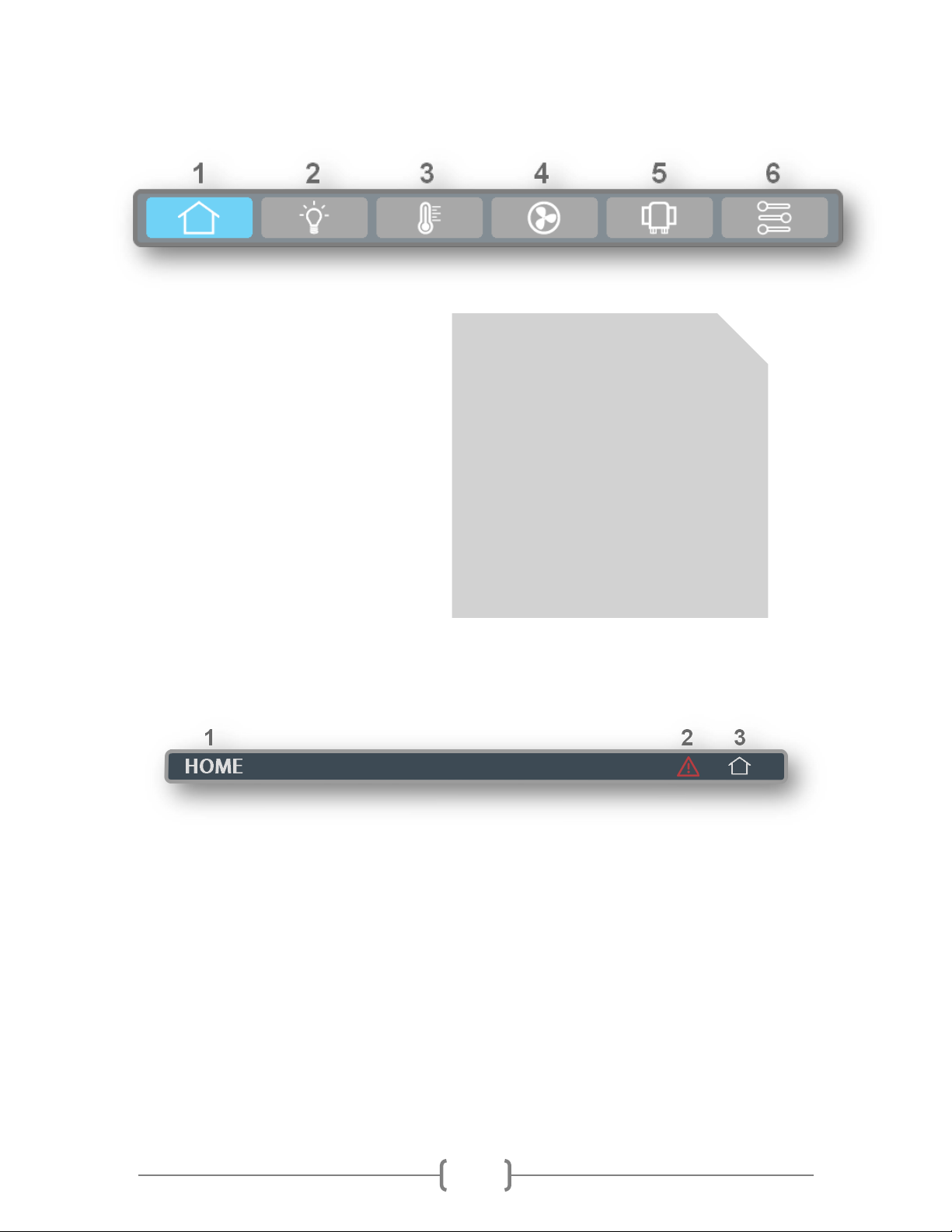
Figure 6 (Bottom Ribbon)
1. Home Page
2. Lights Page
3. Climate Page
4. Fans/Mechanical Page
5. Slides Page
6. Settings Page
Figure 7 (Top Ribbon)
1. Page Designation
▪This section displays your current page.
2. Active Fault Icon
▪If this Icon is present a fault has occurred in the Spyder system. Press it to jump to the fault page.
3. Home Icon
▪When pressed the screen will return to the home page.
[Ribbon Appearance]
The bar may be changed from icons
(shown above) to text. This is up to the
owner’s preference.
To change the bar style, go to.
Settings > Screen Settings > Ribbon
Options
6/16
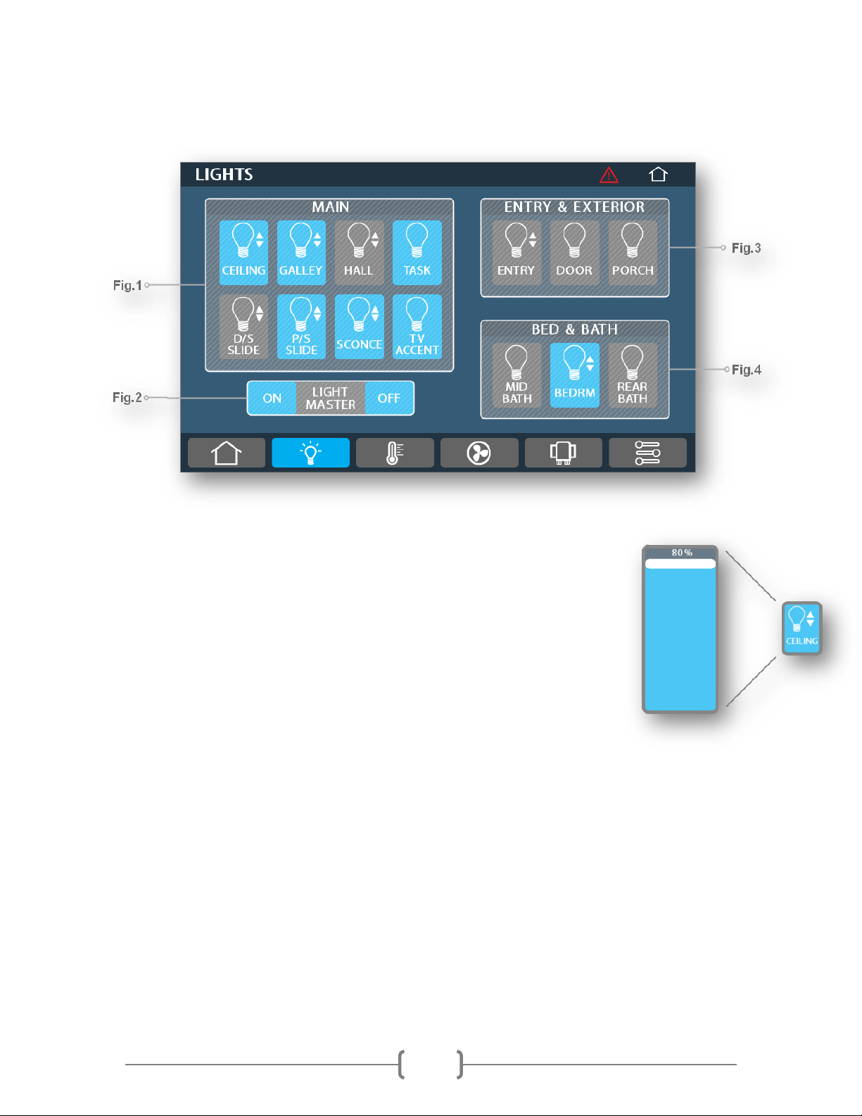
LIGHTING PAGE
Figure 1 (Main)
▪This section allows control over your main interior lights. Any lights that
can dim will contain two arrows beside the light. Holding this light button
will bring up a dimming slider. Drag the slider up and down to set the
desired brightness level.
The light will remember its dimmed value until light master is held on.
When light master is held on all previously dimmed lights will return to full
brightness.
Figure 2 (Light Master)
▪Press light master off to turn off any lights that are currently on in the
coach. Press light master on to turn these same lights back on. Hold light
master on to turn on all interior lights at full brightness.
Figure 3 (Exterior)
▪This section controls all of the lights outside the coach.
Figure 4 (Bed/Bath Lights)
▪This section allows control of your bed lights and bath lights.
7/16
CLIMATE PAGE
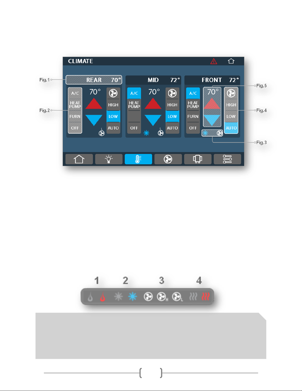
Figure 1 (Zone + Ambient Temperature)
▪This section displays the location of the air-conditioning unit and the ambient temperature in the
zone.
Figure 2 (HVAC Mode Select)
▪This section provides control over your HVAC loads. Press an icon to activate it. For safety and the
longevity of the HVAC system, Most HVAC loads have delays before turning on and off. Zones cannot
have conflicting modes. Hence setting any AC unit to heating while the rest are in cooling will turn
off all AC’s and vise versa.
Figure 3 (HVAC Status)
▪For safety and longevity of the HVAC system delays are put in place between starting and stopping
HVAC loads. These icons display the status of the HVAC system.
[HVAC Icons]
1. Furnace: Off (Grey) On (Red) 3. Fan Status: Fan High (H) Fan Low (L) Fan Off (No Letter)
2. AC: Off (Grey) On (Blue) 4. Heat Pump: Off (Grey) On (Red)

8/16
Climate Page Continued
Figure 4 (Fan Control)
▪This section allows control of the AC fan. When you run the AC in cooling mode you will be able to
select either Fan High, Fan Low, or Auto. Auto mode will control the fan for you choosing the best
time to switch from High to Low. It is recommended having the fan on high or auto when cooling the
coach with the AC. Running the fan on low with the AC on can cause the AC to prematurely freeze
up.
Figure 5 (Temperature Set Point)
▪This section allows control over the HVAC set point in the coach. To heat the coach with your
furnace or heat pumps you must first select heat pump or furnace then set your set point above the
current ambient temperature (Fig.1) To cool the coach you must select AC then set your set point
below the ambient temperature (Fig.1)
9/16
SLIDE PAGE
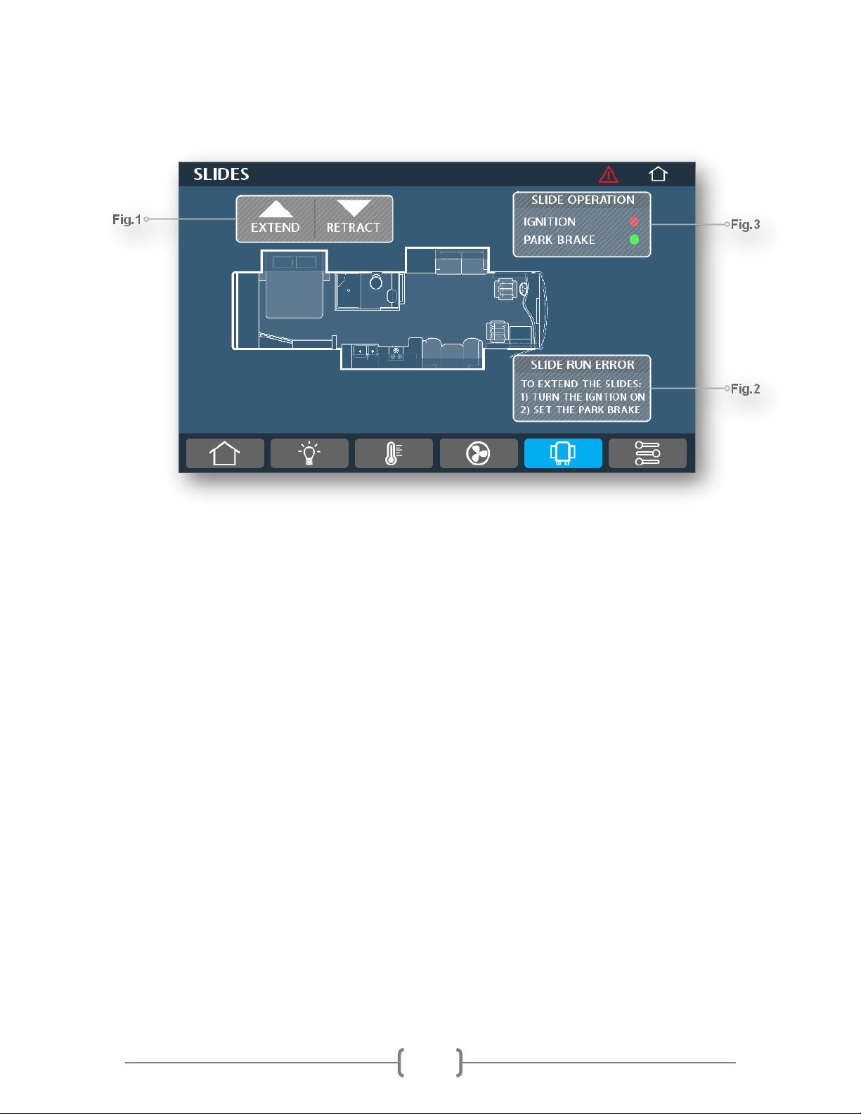
Figure 1 (Slide Extend/Retract)
▪Pressing these buttons will extend and retract your slides if the requirements shown in Fig.2/3 are
met.
Figure 2 (Slide Run Warning)
▪This warning will appear when you try to run your slides if one or more of the following conditions
are not met
▪The ignition is not on
▪The park brake is not set
Figure 3 (Slide Run Requirements Status)
▪This section shows the status of ignition, park brake. All must be green before the slides can retract
or extend.
10/16
MECHANICAL PAGE
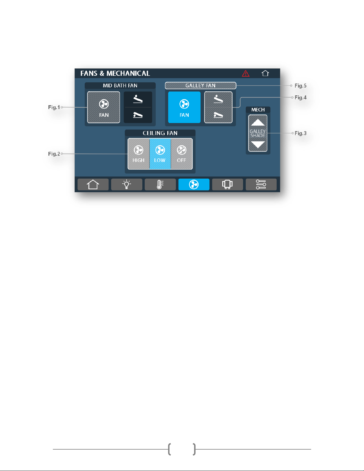
Figure 1 (Fan On / Off)
▪Press this to toggle the selected fan on and off.
Figure 2 (Ceiling Fan Control)
▪This button allows control of the ceiling fan (if applicable). Press the corresponding buttons to
select fan speed.
Figure 3 (Galley Shade Control)
▪When using a shade pressing the up or down arrow will raise the shade all the way up or lower it all
the way down. To adjust a shade to a specific height, press and hold the up or down arrow, then
release at the desired level.
Figure 4 (Fan Lid Up / Down)
▪Press this to raise or lower the vent fan lid. To select an exact vent fan lid position, press and hold
the up ordown arrow on the vent fan. Once you have reached the desired level, release the button.
Figure 5 (Fan Location)
▪This banner indicates the location of the vent fan controlled by the buttons below (if applicable).
Dieses Handbuch passt für folgende Modelle
1
Inhaltsverzeichnis
Beliebte Projektionsfläche Handbücher anderer Marken

FART PRODUKT
FART PRODUKT Standard SCREEN Bedienungsanleitung

Draper
Draper E Series Handbuch

Elite Screens
Elite Screens Elite Tripod Series Bedienungsanleitung

Laarhoven
Laarhoven Companion II Bedienungsanleitung

Renogy
Renogy RMS-LFPS-US Bedienungsanleitung

Da-Lite
Da-Lite ExecutiveElectrol Bedienungsanleitung


