Stanford Research Systems LDC500 Bedienungsanleitung

Operation and Service Manual
Laser Diode Controllers
LDC500 Series
Stanford Research Systems
Revision 4.3 •February 23, 2016

Certification
Stanford Research Systems certifies that this product met its published specifications at the time
of shipment.
Warranty
This Stanford Research Systems product is warranted against defects in materials and workman-
ship for a period of one (1) year from the date of shipment.
Service
For warranty service or repair, this product must be returned to a Stanford Research Systems
authorized service facility. Contact Stanford Research Systems or an authorized representative
before returning this product for repair.
Information in this document is subject to change without notice.
Copyright c
Stanford Research Systems, Inc., 2008 – 2016. All rights reserved.
Stanford Research Systems, Inc.
1290–D Reamwood Avenue
Sunnyvale, CA 94089 USA
Phone: (408) 744-9040 •Fax: (408) 744-9049
Printed in U.S.A. Document number 9-01640-903
LDC500 Series Laser Diode Controllers

Contents
General Information v
Safety and Preparation for Use ................ v
Symbols ............................. vi
Notation ............................. vii
Specifications .......................... viii
1 Overview 1 – 1
1.1 How to use this Manual ................. 1–2
1.2 Introduction to the Instrument ............. 1–2
1.2.1 Instrument architecture ............. 1–2
1.2.2 Grounding ..................... 1–5
1.3 Features and controls ................... 1–6
1.4 Power ............................ 1–6
1.4.1 Power entry module ............... 1–6
1.4.2 Grounding terminal ............... 1–6
1.4.3 Turning on power ................ 1–6
1.4.4 Hardware reset .................. 1–8
1.5 Cable Interfaces ...................... 1–8
1.5.1 Modulate ..................... 1–8
1.5.2 Sync ........................ 1–8
1.5.3 Laser diode .................... 1–8
1.5.4 TEC ......................... 1–9
1.5.5 Remote interface connections .......... 1–10
1.6 User Interface ....................... 1–10
1.6.1 Hard controls ................... 1–10
1.6.2 Dedicated displays ................ 1–11
1.6.3 Alphanumeric display .............. 1–11
1.6.4 Local/Remote ................... 1–13
2 Getting Started 2 – 1
2.1 Preparation for Use .................... 2–2
2.1.1 Power and ground ................ 2–2
2.1.2 Laser diode connections ............. 2–2
2.1.3 TEC module connections ............ 2–2
2.1.4 Checking wiring ................. 2–3
2.1.5 Turning on power ................ 2–5
i

ii Contents
2.2 Operating the TEC controller .............. 2–6
2.2.1 Sensor configuration ............... 2–6
2.2.2 TEC settings .................... 2–7
2.2.3 Verify TEC wiring polarity ........... 2–8
2.2.4 Auto-tuning .................... 2–9
2.2.5 TEC operation in CT mode ........... 2–10
2.2.6 Thermal runaway ................. 2–10
2.2.7 TEC operation in CC mode ........... 2–11
2.2.8 TEC limit values ................. 2–11
2.2.9 Monitoring the TEC ............... 2–12
2.2.10 Configuring TEC trip-offs............ 2–12
2.3 Operating the Laser Diode Driver ............ 2–14
2.3.1 Laser driver configuration ............ 2–14
2.3.2 Laser settings ................... 2–15
2.3.3 Operating the laser in CC mode ........ 2–15
2.3.4 Operating the laser in CP mode ......... 2–16
2.3.5 Modulation .................... 2–17
2.3.6 Monitoring the LD ................ 2–17
2.3.7 Optical power calibration ............ 2–18
2.3.8 Configuring LD trip-offs............. 2–18
2.4 Factory Default Settings ................. 2–19
3 Menus 3 – 1
3.1 Menu Navigation ..................... 3–2
3.2 Laser Menus ........................ 3–2
3.2.1 LD settings .................... 3–2
3.2.2 LD monitor .................... 3–4
3.2.3 LD configuration ................. 3–5
3.3 TEC Menus ........................ 3–7
3.3.1 TEC settings .................... 3–7
3.3.2 TEC monitor ................... 3–8
3.3.3 TEC configuration ................ 3–9
3.4 Other Menus ........................ 3–12
3.4.1 Utility ....................... 3–13
3.4.2 Other messages .................. 3–14
4 Remote Operation 4 – 1
4.1 Index of Common Commands .............. 4–2
4.2 Alphabetic List of Commands .............. 4–6
4.3 Introduction ........................ 4–10
4.3.1 Interface configuration .............. 4–10
4.3.2 Buffers ....................... 4–10
LDC500 Series Laser Diode Controllers

Contents iii
4.4 Ethernet .......................... 4–10
4.4.1 Connection example ............... 4–11
4.5 Commands ......................... 4–16
4.5.1 Command syntax ................. 4–16
4.5.2 Notation ...................... 4–17
4.5.3 Examples ..................... 4–17
4.5.4 Laser limit commands .............. 4–18
4.5.5 Laser setting commands ............. 4–20
4.5.6 Laser monitor commands ............ 4–22
4.5.7 Laser configuration commands ......... 4–24
4.5.8 Laser trip-offcommands ............. 4–29
4.5.9 TEC limit commands ............... 4–31
4.5.10 TEC setting commands ............. 4–33
4.5.11 TEC monitor commands ............. 4–35
4.5.12 TEC configuration commands ......... 4–36
4.5.13 TEC sensor commands .............. 4–40
4.5.14 TEC trip-offcommands ............. 4–45
4.5.15 Interface commands ............... 4–46
4.5.16 Status commands ................. 4–52
4.6 Status Model ........................ 4–57
4.6.1 Status byte (SB) .................. 4–58
4.6.2 Service request enable (SRE) .......... 4–59
4.6.3 Standard event status (ESR) ........... 4–59
4.6.4 Laser diode condition (LDCR) ......... 4–60
4.6.5 TEC controller condition (TECR) ........ 4–61
5 Error Messages 5 – 1
5.1 Laser Diode Driver Messages .............. 5–2
5.1.1 Interlock ...................... 5–2
5.1.2 Transitions with high photodiode current . . . 5 – 2
5.1.3 Transitions with limited laser current ..... 5–2
5.1.4 Transitions locked out .............. 5–2
5.1.5 Responsivity ................... 5–3
5.1.6 Photodiode current overflow .......... 5–3
5.1.7 Responsivity underflow ............. 5–3
5.1.8 Responsivity overflow .............. 5–4
5.1.9 Trip-offfromTEC................. 5–4
5.1.10 Trip-offfrom temperature ............ 5–4
5.2 TEC Messages ....................... 5–4
5.2.1 Autotune ...................... 5–4
5.2.2 No loop control .................. 5–5
5.2.3 Transitions locked out .............. 5–5
LDC500 Series Laser Diode Controllers

iv Contents
5.2.4 Temperature faults ................ 5–6
5.2.5 Thermal runaway ................. 5–6
5.2.6 Polarity change locked out ........... 5–6
5.3 Other messages ...................... 5–6
5.3.1 Restart ....................... 5–6
6 Accessories 6 – 1
6.1 Cables ........................... 6–2
6.1.1 Laser diode cables ................ 6–2
6.1.2 TEC cables ..................... 6–4
LDC500 Series Laser Diode Controllers

General Information
Safety and Preparation for Use
Dangerous voltages, capable of causing injury or death, are
WARNING present in this instrument. Do not remove the product covers
or panels. Do not apply power or operate the product without
all covers and panels in place.
AC line voltage
The LDC500 Series Laser Diode Controllers operate from a 100 V,
120 V, 220 V, or 240 V nominal AC power source having a line fre-
quency of 50 Hz or 60 Hz. Before connecting the power cord to a
power source, verify that the LINE VOLTAGE SELECTOR, located
in the rear panel power-entry module, is set so that the correct AC
line voltage value is visible.
The LDC500 Series Laser Diode Controllers will be damaged if oper-
CAUTION ated with the LINE VOLTAGE SELECTOR set for the wrong AC line
voltage, or if the wrong fuses are installed. Verify that the correct
line fuses are installed before connecting the line cord. Fuse size is
5MF “fast blow” (5×20 mm). For 100 V/120 V, use 4 A fuses; for
220 V/240 V, use 2 A fuses.
Line cord
The LDC500 Series Laser Diode Controllers have a detachable, three-
wire power cord for connection to the power source and to a protec-
tive ground. The exposed metal parts of the instrument are connected
to the outlet ground to protect against electrical shock. Always use
an outlet which has a properly connected protective ground.
Service
The LDC500 Series Laser Diode Controllers do not have any user
serviceable parts inside. Refer service to a qualified technician.
Do not install substitute parts or perform any unauthorized modi-
fications to this instrument. Contact the factory for instructions on
how to return the instrument for authorized service and adjustment.
v

vi General Information
Symbols you may Find on SRS Products
Symbol Description
Alternating current
Caution - risk of electric shock
Frame or chassis terminal
Caution - refer to accompanying documents
Earth (ground) terminal
Battery
Fuse
On (supply)
Off (supply)
LDC500 Series Laser Diode Controllers

General Information vii
Notation
The following notation will be used throughout this manual.
Unless otherwise specified in the text, LDC500 refers generally to
either the LDC500, LDC501, or LDC502 Laser Diode Controller.
A warning means that injury or death is possible if the instructions
WARNING are not obeyed.
A caution means that damage to the instrument or other equipment
CAUTION is possible.
Typesetting conventions used in this manual are:
•Front-panel buttons are set as [Button].
•Front-panel indicators are set as Overload.
•Remote command names are set as *IDN?.
•Literal text other than command names is set as OFF.
Remote command examples will all be set in monospaced font. In
these examples, data sent by the host computer to the LDC500 are set
as straight teletype font, while responses received by the host
computer from the LDC500 are set as slanted teletype font.
LDC500 Series Laser Diode Controllers

viii General Information
Specifications
All performance specifications after 1 hour warm-up at 25 ◦C ambi-
ent.
Laser diode current source
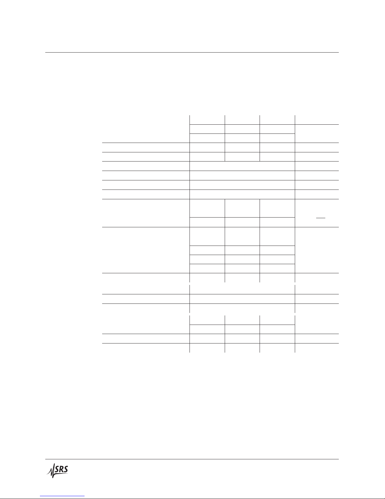
LDC500 LDC501 LDC502 Units
Output current Range, high 0–100 0–500 0–2000
low 0–50 0–250 0–1000 mA
Setpoint resolution 1 10 100 μA
Accuracy ±10 ±50 ±200 μA
DC output impedance 1 MΩmin
Thermal drift ±10 ppm/◦C max
Short-term stability (1 hr) ±5 ppm FS
Long-term stability (24 hr) ±15 ppm FS
Noise density [1]
high range 0.7 3.5 12.5
low range 0.4 1.8 6.3 nA/√Hz typ.
Wide band noise [2]
high range, high BW 0.9 4.5 25
high range, low BW 0.6 1.5 5.0
low range, high BW 0.5 2.3 10
low range, low BW 0.3 1 3.5 μA rms max
Power fail transient [3] 1 1 5 mA max
Compliance voltage Range 0.1–10 V
Resolution 10 mV
Accuracy +0.2 V
Output current limit Range, high 0–100 0–500 0–2000
low 0–50 0–250 0–1000 mA
Resolution 10 10 100 μA
Accuracy ±100 ±100 ±400 μA
LDC500 Series Laser Diode Controllers
Dieses Handbuch passt für folgende Modelle
2
Inhaltsverzeichnis
Andere Stanford Research Systems Controller Handbücher