SteppIR WIRELESS Handbuch

1
WIRELESS REMOTE BOARD
SETUP INSTRUCTIONS

2
Welcome
The wireless remote board removes the need for lengthy control cable and eliminates concerns of
lightning damage to your controller. It accomplishes this by replacing the Cat 5 cable with Green
Heron Everywhere radio links. The controller can sit next to the radio while the remote driver is
located at the base of the tower.
If you purchased a new controller with the wireless remote board, your controller and remote
board are paired and ready for setup. Skip to page 13 and proceed with setup and installation.
If you purchased the wireless remote board as an upgrade to an existing controller or
controller/tethered remote board pair, then there are some additional steps that you will need to
go through to modify your controller.
GHE Radio Setup
Your wireless link boards will arrive programmed to the same channel. However, if you plan on
using more than one controller with a radio link they will need to be on different channels. Also, if
you are using XBee radios for other controls they must be on different channels. The following
instructions walk you through the setup process for the XBee radios.
Fig. 1 XBee radio and USB adapter
You will need 2 XBee radios, the USB adapter and XCTU configuration software.
Step 1: Plug a radio into the USB adapter and connect the mini USB.
Step 2: Start XCTU software.
Step 3: Select the Discover Radio Modules icon.
Step 4: Select the com port the radio is connected to and select Next.
Step 5: Leave the default settings and select Finish.
Step 6: Wait for the program to find the radio and then select Add Selected Device.
Step 7: Set the Channel using the configuration tab.
Step 8: Press Write and disconnect the USB.
Step 9: Repeat steps 4 through 9 with the second radio.
Step 10: Install the one radio in the SDA controller.
Step 11: Install the other radio on the remote driver board.

3
Controller Modification
If you purchased the wireless remote board as an upgrade to an existing controller (or
controller/tethered remote board pair) you will need to modify the controller to install the wireless
board and antenna.
Step 1: Disconnect the controller from any power source. Then disconnect the antenna control
cable.
Step 2: Remove the cover from the controller by unscrewing the four screws (two on each side).
Step 3: Unplug the display board from the driver board by disconnecting the 20 pin IDC cable that
connects them.
Step 4: Unscrew the screws holding the driver board to the controller and remove the driver
board. There will be two or three philips head screws holding the board to the bottom of the
controller and two or more hex screws on the back.
Step 5: Using the following diagram as a guide, drill a ¼ inch hole in the back of the controller
chassis. The exact placement of the hole is not important.
Fig. 2 Antenna hole location.

4
Step 6: Prepare the included 6” length of flat ribbon cable to connect the driver board and the
remote board. This cable will have a 2x4 IDC socket on one end, and the other end will need to
have the wires 1, 2, 6, 7, and 8 separated, stripped, and tinned to prepare for soldering. Note: The
ribbon cable has a red wire on one side. That red wire is wire #1, the one next to it is #2, and so on.
Fig. 3 Ribbon cable
Step 7: Locate the area shown inside the red box in Figure 4.
Fig. 4 Driver Board Pad Locations
5
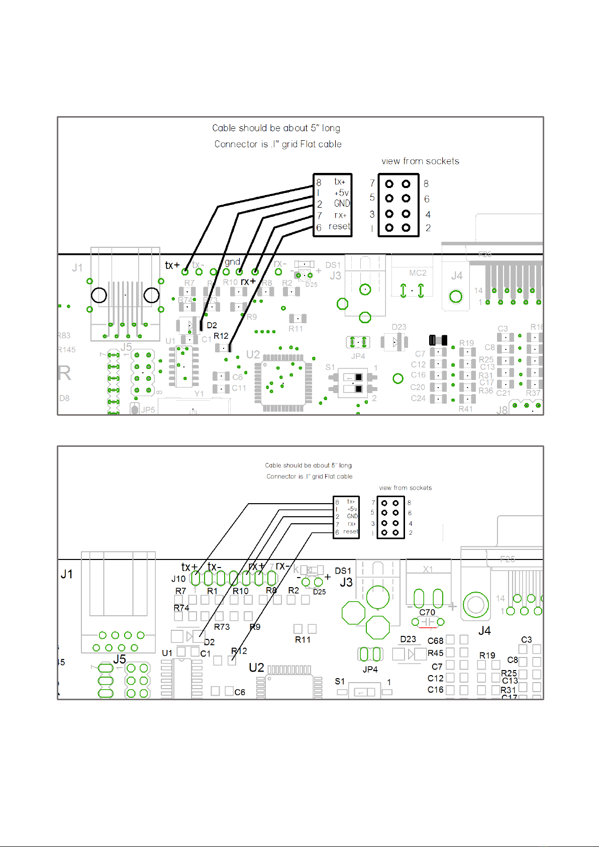
Step 8: Solder the ribbon cable to the driver board based on the schematics below. The specific
connections are shown in Figure 5 and Figure 6. Note: If you have an ALP driver board, refer to
Figure 5. Refer to Figure 6 if you have a standard driver board.
Fig. 5 ALP driver board pad locations.
Fig. 6 Standard driver board pad locations.

6
Step 9: Screw the included jack screw and fiberglass washer into the existing standoff on the driver
board as shown in Figure 7. Note: If the driver board has a relay board installed, omit the washer.
Fig. 7 Jack screw installed in hex standoff.
Step 10: Place the driver board back into the controller chassis.
Step 11: Place the mounting bracket on the driver board, aligning with the jack screw and
mounting holes.
Fig. 8 Mounting bracket with GHE remote board and Wi-Fi module installed.

7
Step 12: Screw the mounting bracket to the driver board using the included pan head screws as
shown in figure 9. One screw will fix the mounting bracket and driver board to the controller
chassis, and the other will fix the mounting bracket to the standoffs installed in step 9.
Fig. 9 Install the indicated screws.
Step 13: Screw the countersunk Phillips head screw you removed in step 4 back into the chassis,
fixing the driver board in place.
Fig. 10 Install the indicated screw.

8
Step 14: Plug in the display board by connecting the 20 pin IDC cable into the socket on the driver
board.
Step 15: Plug the 8-pin ribbon cable into 8-pin TTL connector as shown in Figure 11. Make sure the
wire is oriented the correct direction!
Fig. 11 Proper orientation of ribbon cable.
Step 16: Mount the antenna extension in the 1/4” hole you previously drilled into the metal frame.
Fig. 12 Antenna installed in chassis.

9
Step 17: Plug the other end of the antenna extension into the connector on the Wi-Fi board.
Fig. 13 Wi-Fi antenna connection
Step 18: Replace the cover of the controller.
Remote Board Modification
If you own a tethered remote board and purchased the wireless remote board as an upgrade, you
will need to modify your tethered remote board.
Step 1: Unscrew the pan head screws from the aluminum mounting bracket. (If a relay board is
installed, remove the pan head screws holding the relay board as well.)
Fig. 14 Tethered remote board. Remove the indicated screws.

10
Step 2: Screw the 3/8” jack screw into the hex standoff with a washer in between. If the driver
board has a relay board installed, omit the washer.
Fig. 15 Jack screw installed with fiber washer
Step 3: Place the mounting bracket on the driver board, aligning with the standoff and mounting
holes.
Step 4: Screw the mounting bracket to the driver board using a pan head screw, as shown in Figure
16.
Fig. 16 Wi-Fi board installed on remote driver board.
Inhaltsverzeichnis
Beliebte Konferenzsystem Handbücher anderer Marken

Kramer
Kramer VIA GO Bedienungsanleitung

AVT
AVT MAGIC AC1 Go Bedienungsanleitung

ProSoft Technology
ProSoft Technology AN-X4-AB-DHRIO Bedienungsanleitung

Sony
Sony PCS-I150 Bedienungsanleitung

Middle Atlantic Products
Middle Atlantic Products VTC Series Bedienungsanleitung

Prentke Romich Company
Prentke Romich Company Vanguard Plus Leitfaden


