
Stroco 15.00 M Betriebsanleitung

SERVICE INSTRUCTIONS
for fuel-burning heater type
STROCO 15.00 M
Applicable from heater no.
12V: 238
24V: 405
STROCO ApS, Viborgvej 50, Voldby, DK-8450 Hammel, ph. +45 86961066, fax +45 86969647
Technical approval no. SP 555 AD 06
EU directive 42/245:
EU technical approval no. E5 10R-03152
Heating directive E 2001/56:
EU technical approval no. R122 E5 00002
ISO certified
Developed with aid from the Danish Environmental Protection Agency
GB 04/18
This manual is also available at www.stroco.dk


IMPORTANT
PAGE 3
The minimum conditions below must be met in order to
maintain the right to claims under the warranty.
1. Installation must be carried out as described in this manual.
2. Service and maintenance must be performed in a proper
professional manner. Maintenance/service must be
performed within the established schedule.
3. Only original spare parts may be used.
4. The heater may only be used for the type of fuel stated on
the model plate.
5. The heater may only be used with the voltage stated on the
model plate.

The heater must not be used in service stations.
The heater must not be used where there is risk of ignition of
flammable vapours and/or materials. Nor where there is risk
of accumulation of toxic gasses, e.g. in closed spaces.
The heater must not be used if the heater or its exhaust
opening is near flammable materials, e.g. dry grass.
IMPORTANT
PAGE 4

CONTENTS
PAGE 5
PAGE:
Description ………………………………………………………………… 6-7
Schematic diagram of fuel-burning heater ………………………………... 7
Built-in dimensions …………………………………………………………. 8
Installation guide/installation plan ...…………………………………... 9-10
List of connections .………………………………………………………… 11
Electrical connections ....…………………………………………………... 12
Technical specifications ………………………………………………... 13-14
Explanation of terminology ..……………………………………………… 14
Maintenance …………………………………………………………….. 15-16
Description of functionality - operation ..………………………………… 17
Description of functionality ..……………………………………………… 18
Troubleshooting - how? …………………………………………………… 19
Dismounting burner and combustion chamber ..………………………... 20
Process control diagram ....………………………………………………... 21
Alarm functionality ....……………………………………………………... 22
Combustion unit .…………………………………………………………... 23
Voltage control of electrodes .……………………………………………... 24
Photoelectric sensor ...……………………………………………………... 25
Under/overvoltage ..………………………………………………………... 26
Replacing the fan motor …………………………………………………... 27
Checking the fuel pump solenoid valve …………………………………... 28
Operating thermostat sensor .……………………………………………... 29
Assembly drawing - parts list ..………………………………………… 30-31
Electrical diagram ……………………………………………………… 32-33
Installation in boats ..…………………………………………………… 34-36
Warranty conditions .……………………………………………………… 37
Dealers .……………………………………………………………………... 38

DESCRIPTION
PAGE 6
It is important to read and understand this manual before using the STROCO heater to ensure
optimum utility and safety. Please mail the warranty card to STROCO ApS.
The presence of the above-mentioned basic elements, in the right quantities and correct mixtures, is
essential to the heat production of the STROCO heater.
In case of failure or unsatisfactory operation, make sure to check these basic elements first.
The STROCO heater is independent of the operation of the vehicle’s engine, and vice versa. This
means that interruptions in one system do not affect the operation of the other. However, lack of
electrical power or fuel will affect both systems, if both engine and heater are connected to the same
battery and fuel tank.
The fuel-burning heater’s job is to heat the water in the heating system. It does this by burning fuel
at a high temperature in the combustion chamber. This heat is transferred to the water in the boiler
section of the heater, and the water is pumped into the heat exchanger units in a continual process,
where the hot water acts as a transfer agent between heat production (the heater) and heat
exchangers.
The heart of the heater is the combustion section. Fuel is pumped to here and vaporized by a nozzle.
This fuel vapour ignites, establishing a flame (combustion). One of the factors that ensure correct
combustion of the fuel vapour is regulation of air intake. The combustion process and other function-
ality of the heater is controlled by the brain of the system: the electronic control and monitoring unit.
This automatic system ensures that the process follows predetermined routines. If the process should
deviate from these routines, or if the combustion process fails or becomes deficient due to poor
supply of the basic elements - fuel, water, and air - the system shuts down the process. In theory, the
presence of the basic elements alone should ensure the combustion process, but since we require the
process to be highly efficient and reliable, it must run in a controlled manner. This manual will help
you to keep the heater running satisfactorily at all times. What to do if the heater is not working, or
performs inadequately?
The section Alarm Functionality can help you to locate the source of an error and analyse the
symptoms.
The section Error Remedy Instructions in the Description of Functionality explains and illustrates
remedial actions.
Fuel
Water
Electrical power
Air
Heat
+=
PAGE 7
Precautionary measures are always better than repairs, and there are a number of Maintenance
Procedures that should be undertaken regularly to ensure the continued working order of the heater.
Please consult the maintenance section. Section 1 in the manual deals with the installation of the
heater, i.e. the actual fitting. The other sections deal with servicing and maintenance exclusively.
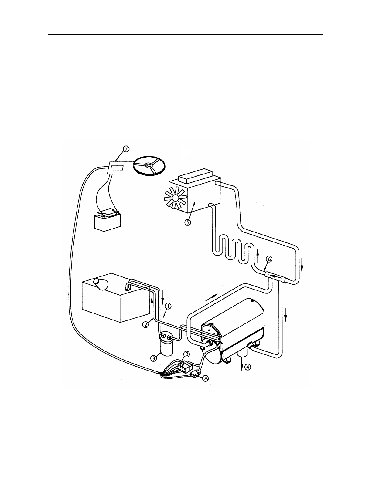
Schematic diagram of fuel-burning heater
1: Supply, diesel fuel, 2: Return, diesel fuel, 3: Filter, 4: Exhaust, 5: Engine, 6:Heating system,
7:Control panel

BUILT-IN DIMENSIONS
PAGE 8
All measurements +/- 2 mm.

PAGE 9
INSTALLATION GUIDE/INSTALLATION PLAN
In general: Installation must be performed in accordance with the ECE 2001/56 standard
These instructions apply to STROCO fuel-burning heater, type 15.00 M.
Material and design of fuel hoses/pipes: TA max. -40°C/+120°C.
In case of replacement of hoses, use ONLY hoses from STROCO ApS, or hoses approved by
STROCO ApS. The heater’s warranty will be void if any other hoses are used. Leaky hoses and
joints lead to increased risk of fire.
Non-insulated exhaust pipes/hoses must have at least 7.5 cm to flammable material.
Fuel hoses placed on the outside of the vehicle must be screened to prevent any damage. Electric
cables may not be placed next to fuel hoses.
The fuel-burning heater should be mounted where it is protected from water and spatter from the
vehicle’s wheels, and from impact or other damaging effects. It is very important to clean the sur-
rounding area thoroughly when servicing the unit, and to check all electrical connections and
plugs, greasing with acid-free grease. The area should be kept free of damp. Covers, casings etc.,
must not be removed.
The heater must be positioned in an way that does not impede maintenance work on the heater and
the vehicle’s other components. If necessary, the heater must be placed in a separate box.
Installation must be performed in such a way that heat impact from the vehicle’s engine and ex-
haust system does not damage the heater. Conversely, the vehicle’s components must be protected
against damage from the heater’s exhaust.
Electrical installations for the heater must comply with SEN 3607111 ”Electric installations for
motor vehicles” or similar.
The water system which the heater will be connected to must be fitted with a pressure control valve
for safety.
The heater should be installed in as low a position as possible relative to the vehicle’s cooling/
heating system.
If the heater is installed inside a casing, this must have an air intake opening of at least 75 cm².
(The air intake must not be blocked off). The casing must be made from a non-flammable material.
Intake air for the heater must not come from rooms where there are people. The placement of the
intake must be such that exhaust gas from the vehicle does not mix with the intake air.
The air intake must be placed and designed to avoid clogging by snow or dirt. The air intake must
be placed to keep the airflow around the vehicle from interfering with the pressure in the system.
Place the orifice of the exhaust pipe so that the combustion is not materially affevted by airflows
around the vehicle to prevent heating damage on adjacent vehicle components, and to prevent igni-
tion of grass, etc.
The exhaust pipe must be designed to work with local exhaust ventilation, although not directly
connected, as this can affect combustion.

INSTALLATION GUIDE/INSTALLATION PLAN
PAGE 10
The vehicle must have safety measures to ensure that no exhaust ends up in rooms where there are
people.
The exhaust pipe should be max. 4000 mm in length and should be 65 mm in diameter.
If the heater is mounted in driver, passenger or storage room, this part of the fuel line must be
made from solid-drawn pipe steel. Connection to the fuel supply of the vehicle must be established
outside these rooms.
If the heater is mounted in driver or passenger rooms, the air inlet must be led to fresh air.
The exhaust pipe should be made from a material that resists heat and corrosion
(AISI 304 SS 2333 alloy steel resistant to max. 800°C with at least 0.75 mm wall thickness).
Connections to the exhaust system must be tight and secured with brackets.
If the heater is installed in a cargo area, the exhaust must be made from an unbroken steel pipe.
After installation, the model plate must be accessible and readable.
THE EXHAUST MUST BE ROUTED OUTSIDE OF THE VEHICLE IN HOSE OR PIPE.
There should be adequate room at the combustion end of the heater to remove the combustion unit
and combustion pipe. Minimum distances are shown in the illustration. We recommend mounting the
heater unit on vibration dampers. In this case, the heater connections should be made with flexible
hoses.
Inhaltsverzeichnis
Andere Stroco Heizung Handbücher


Beliebte Heizung Handbücher anderer Marken


Empire Heating Systems
Empire Heating Systems WCC65 Bedienungsanleitung

Wetekom
Wetekom 92 86 43 Bedienungsanleitung

Desa
Desa SPC170-F Bedienungsanleitung

Watlow
Watlow Watrod Electric Tubular Heaters Bedienungsanleitung

Haverland
Haverland ECO-DRY GPS Series Stücklistenhandbuch

Stelpro
Stelpro ASILVC2060 Series Bedienungsanleitung