Superwinch Certus Wireless Bedienungsanleitung

*+ # i
Superwinch LLC.
359 Lake Road
Dayville, CT 06241, USA
tel: 1.860.928.7787
fax: 1.860.963.0811
www.superwinch.com
Superwinch LTD.
Union Mine Road
Tavistock, Devon PL19 0NS
England
tel: +44 (0) 1822 614101
fax: + 44 (0) 1822 615204
98-17449 Rev - 01/24/2012
OWNER’S MANUAL
READ AND UNDERSTAND THIS MANUAL BEFORE
INSTALLATION AND OPERATION OF YOUR
SUPERWINCH PRODUCT
CAUTION
!
TM
WIRELESS REMOTE CONTROL
1
SPANISH

WARNING
!
CERTUS WIRELESS REMOTE SYSTEM – CONSUMER VERSION
Read and understand the manual thoroughly before installing or
using the radio remote control.
General Information
The system operates on a frequency of 433MHZ and utilizes frequency modulation generally known
as FM technology. While an FM signal is much less susceptible to electrical interference than an
AM signal, there can never be total protection against outside interference. Interference can result
from the turning on and o of electronic equipment and can come from proximity to industrial
equipment and types of computer equipment. The greatest range will be achieved if the receiver is
not enclosed in metal.
SAFETY PRECAUTIONS
The responsibility for safe installation and operation of this system ultimately rests
with you, the operator. Read and understand all safety precautions and operating
instructions before installing and operating the system. Careless system operation can
result in serious injury and/or property damage.
Throughout this manual, you will nd notations with the following headings:
Indicates an imminently hazardous situation which, if not
avoided, will result in death or serious injury.
Indicates a potentially hazardous situation which, if not
avoided, could result in death or serious injury.
Indicates a potentially hazardous situation which, if not
avoided, may result in minor or moderate injury. This
notation is also used to alert against unsafe practices.
CAUTION
!
DANGER
!
Read Owner's
Manual
Note: Indicates additional information in the installation and operation procedures of
your wireless remote control.
The following symbols on the product and in the Owners manual are used:
WARNING
!
2
Improper installation or improper use of the remote unit by the user
could result in injury or destruction of property. Keep this manual for
future reference.
SPANISH

Misuse or abuse of this equipment could result in injury to the user or others
and/or damage to property.
The control will be brought to a stop if:
1. the red power button is activated
2. system encounters the same frequency from an outside source
3. ve minutes go by since the last transmission
These safety features are engineered into
the system to protect personnel and
equipment and should never be changed,
taken out or bypassed.
If an emergency situation arises immediately
press the red power button on the transmitter
see (Fig. 1)
1. Never leave the transmitter unattended.
2. The transmitter is only to be used where there is a clear view of the operating
machinery.
3. Do not use more than one transmitter for one receiver box. If you own or
purchase a backup transmitter it is important to stow the second transmitter
securely. When the system is rst put into use, the backup unit should be tested
then have its battery removed and the unit should be stored in a secure place
to avoid accidental operation, which may result in serious injury or death.
4. Both the transmitter housing and buttons should be checked on a regular
basis and, if damaged, the transmitter should be taken out of use.
5. In an emergency situation, pressing the red stop button should immediately
activate the stop relay in the receiver. Remove power to the machine.
3
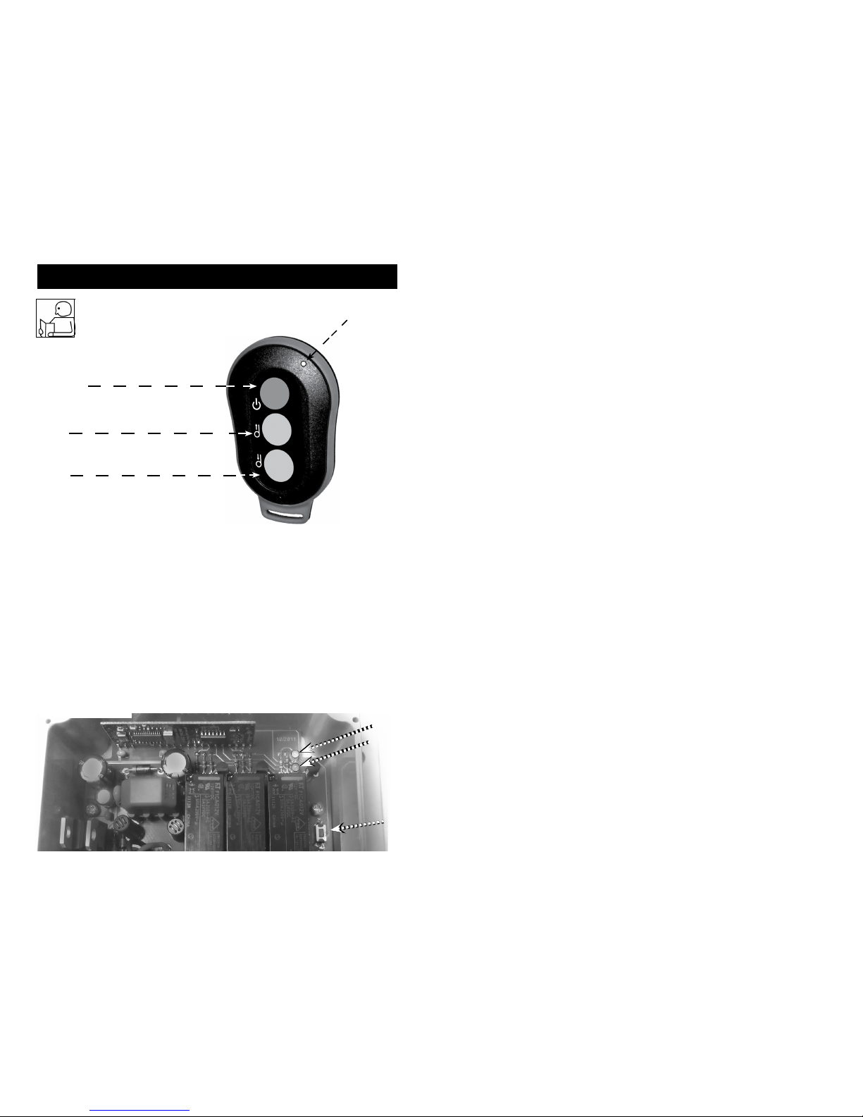
Fig. 1
LED 1
Power Button
SPANISH
!
AVERTISSEMENT
SPANISH
Programming the Transmitter
Note: Transmitters supplied with the unit are pre-programmed at the factory -
DO NOT RE-PROGRAM THEM.
Should a new transmitter be purchased it will require programming.
To program, follow the instructions below:
NOTE: Each of the three (3) buttons needs to be programmed individually
OPERATION INSTRUCTIONS
RED
Power
Button
Green
Button
1
Green
Button
2
LED 1
(Fig. 2)
Front of Transmitter
Green LED
Red LED
Program Green Button 1:
• Press the learn button (See Fig.3 below) 1 time.
Wait for the red LED on receiver to ash 1 time.
• Press green button 1 on the transmitter and release.
• Re-press green button 1 on the transmitter.
The red LED on receiver will now ash to indicate that learning is complete for
green button 1.
Learn
Button
(Fig.3)
4

The transmitter has one red LED light, see (Fig. 2) which glows when any one
of the buttons is depressed; this shows the receiver is sending a signal to the
receiver.
1. To use the wireless system, the operator rst activates the system by pressing
the red power button on the transmitter; a green LED on the receiver will
glow as the system is now in operational mode and ready for use.
2. To deactivate the wireless system, press the red power button and the green
LED on the receiver turns o as the system is now in standby mode.
3. The power button always has priority and will override all buttons so that it
will put the system into standby mode.
4. If the system is idle for 5 minutes or longer, the system will deactivate and go
into standby mode and will need to be activated prior to use.
Program Red Power Button:
• Press the learn button 1 time
Wait for the red LED on receiver to ash 1 time
• Press the learn button 1 more time
Wait for the red LED on receiver to ash 2 times
• Press the learn button 1 more time
Wait for the red LED on receiver to ash 3 times
• Press the red button on the transmitter and release
• Re-press the red button on the transmitter
The red LED on receiver will now ash to indicate that learning is complete for
the red button
Your transmitter is now programmed and ready for use
Program Green Button 2:
• Press the learn button 1 time
Wait for the red LED on receiver to ash 1 time
• Press the learn button 1 more time
Wait for the red LED on receiver to ash 2 times
• Press green button 2 on the transmitter and release
• Re-press green button 2 on the transmitter
The red LED on receiver will now ash to indicate that learning is complete
for green button 2
5
SPANISH

The folowing funtions are built into the system :
1. Standby mode:
When hooked up to the supply voltage, the system is in standby mode
2. Operational mode:
When the system is in operational mode, the green LED on the receiver will
glow and the system is now ready for use.
3. Automatic stop with frequency interference:
The system will automatically move to standby mode when another
transmitter with the same frequency is detected.
Battery
To change the battery, open the back of the transmitter by removing the two
(2) small screws. After removing the cover, carefully remove the old battery and
replace it with a new CR2450 3 volt coin cell battery. Before installing the new
battery insure that the connector is free from corrosion. Corrosion can
be easily removed using a small sti brush. After the new battery has been
installed, replace the cover carefully by means of the two small screws.
After changing the battery make sure the rubber
seal on the transmitter is in place correctly or the sealing of the unit cannot
be guaranteed. Used batteries should be disposed of according to national
regulations.
CAUTION
!
The transmitter and receiver utilize an internal antenna. This antenna cannot be
shortened, moved or otherwise altered. Alteration will void warranty and may
cause erratic operation.
For safety reasons the receiver also moves to standby mode when more than 5
minutes has elapsed between signals from transmitter to receiver.
The green LED is on when the receiver is on and functional. The red LED ashes
when a button on the transmitter is being pressed.
The receiver works with 3 relays, 2 for direction and 1 for on/o. The relays
switch the current to the proper switch output
6
SPANISH

Do not attempt to install wiring when the battery is connected.
Do not lean over battery while making connections.
Automotive batteries contain ammable and explosive gases. Wear eye
protection during installation and remove all metal jewellery.
7
Ensure that the wiring harness does not interfere or come in
contact with any hot or moving engine, suspension, steering,
braking or exhaust parts.
CAUTION
!
INSTALLATION INSTRUCTIONS
Step 1
Disconnect the battery before beginning installation.
Step 2
Locate a place to mount the Wireless Control unit. Under dash, console, or inside
wall of a box trailer would be typical locations. The unit can be mounted in any
orientation inside the vehicle or trailer. The unit can be mounted by either
cable ties or four (4) self-tapping screws.
Step 3
Connect the white weather pack connector end of the harness to the mating
white weather pack connector on the wireless receiver module. see ( Fig. 4)
Step 4.
For P/N 06705
A. Connect the winch plug end to your Talon winch socket.
For P/N 06707 (See Fig.5)
A. Connect the black wire ring terminal from the harness assembly to
the black (-) stud of the solenoid.
C. Connect the red wire ring terminal from the harness assembly to the
red (+) stud of the solenoid.
D. Use one of the two supplied quick splice connectors to splice the
blue wire from the harness assembly into the black wire from the
handlebar rocker switch.
E. Use the second quick splice connector to splice the yellow wire from
the harness assembly into the green wire from the handlebar rocker
switch.
from the Winch to the Receiver
DANGER
!
Fig. 4
SPANISH
Step 5. Install battery that came with your control (see battery section)
For P/N 06709:
A. Connect the winch plug end to your S-Series winch socket.

After mounting and wiring is complete, test the operation of the system to be
sure that the winch is operating in the proper direction utilizing the transmitter.
If not, troubleshoot.
1. Press the red power button on the transmitter to activate the system.
2. Check to see that the operation of the transmitter corresponds to the opera
tion of the winch.
3. Check the power function. After pressing the red power button, the winch
should not be able to be controlled by the transmitter.
4. If the checks are nished and everything is functional, the system is opera
tional.
Check to ensure that the ground and positive leads from
the battery are disconnected before performing any
electrical work.
OPERATION TEST
WARNING
!
(Fig. 5)
BLACK Wire
from
Harness
Assembly
RED Wire
from
Harness
Assembly
GREEN Wire from
handle bar switch
(green wire passes
through connector)
Splice Connector Splice Connector
YELLOW Wire from
Harness Assembly
(closed o side of
connector used)
BLACK Wire from
handle bar switch
(black wire passes
through connector)
BLUE Wire from
Harness Assembly
(closed o side of
connector used)
8
SPANISH

9
MAINTENANCE
Depending on use, the batteries in the remote transmitter will need
replacement after a period of time.
No other regular maintenance is required.
Receiver shows no
reaction after supply
current has been
connected and Green
LED does not light up
when power button
on transmitter is pressed
Receiver shows no
reaction after current
is supplied and button
on transmitter is pressed
Green LED is on but Red
LED does not light up
when Green button 1 or
2 is pressed
Receiver can be taken
out of standby mode
but quickly shuts down
again
System does not have
enough eective range
Supply current not
available /
Connections reversed
Transmitter not
programed correctly to
receiver
Another source is
transmitting on the same
frequency
Receiver mounted
incorrectly /
Receiver surrounded in
metal /
Weak battery
TROUBLESHOOTING
Check polarity /
Test current
into receiver /
Turn on main
power.
Re-program transmitter
(see page 4-5)
Deactivate other
transmitter
See Mounting instructions
Change battery
Problem Possible Cause Solution
SPANISH
System does not operate
in the proper direction
Harness wired
incorrectly
Verify connections per
installation instructions

Frequency FM 433 MHz
Voltage 12-24 Volt DC
No signal current 12V 25mA, 24v 35mA
Max. operating voltage 24VDC
Antenna Internal wire
LED Ready mode Green
LED Signal Red
Dimension 5.1” x 2.8” x 2.0” (130mm x 70mm x 50mm)
Ingress Protection IP67
Operational Temperature -4° F to 122° F (-20° C to + 50° C)
Technical Data - Receiver
Technical Data - Transmitter
Frequency FM 433 MHZ
Number of Functions 2, plus Power function
Antenna Multilayer Chip
LED Light for transmission Red
Dimensions
3.3” x 2.1”x .07” (84mm x 53mm x 18mm)
Ingress Protection Level IP66
Operational Temperature -4° F to 122° F (-20° C to + 50° C)
10
SPANISH
Inhaltsverzeichnis
Sprachen:
Beliebte Fernbedienung Handbücher anderer Marken

Panasonic
Panasonic EUR7622KB0 Bedienungsanleitung

Bang & Olufsen
Bang & Olufsen Beo4 Bedienungsanleitung

Sunwave Tech.
Sunwave Tech. RemoteComm SRC-7000 Bedienungsanleitung

Multiplex
Multiplex PROFI TX 9 Bedienungsanleitung

One Remote
One Remote RMB4 Bedienungsanleitung

FUTABA
FUTABA 9ZAP - PART2 Bedienungsanleitung


