TAIKO AG1000-01 Bedienungsanleitung

AG-1000 User’s Manual
SMS Alert Gateway
All contents are subjected to change without prior notice Rev 7.3
Copyright © 2005 Taiko Network Communications Pte Ltd
UM-AG1000 R7.2
AG1000-01
Revision: 8
SMS Alert Gateway (8 DI 4DO)

AG-1000 User’s Manual
SMS Alert Gateway
All contents are subjected to change without prior notice Rev 7.3
Copyright © 2005 Taiko Network Communications Pte Ltd
UM-AG1000 R7.2
Contents
Guidance for the manual .......................................................................................................................... 1
Section 1 Introduction ........................................................................................................................... 2
1.1 Product Overview ...................................................................................................................... 2
Section 2 Hardware Reference ............................................................................................................. 4
2.1 Connector Description .............................................................................................................. 4
2.2 Hardware Setup ......................................................................................................................... 6
2. LAN Configuration ................................................................................................................... 7
Section Web Configuration ................................................................................................................ 8
.1 Login ........................................................................................................................................... 8
.2 Main ............................................................................................................................................ 9
. Group List ................................................................................................................................ 10
.4 Point List .................................................................................................................................. 11
.5 Edit Profile ............................................................................................................................... 13
.6 Event Log ................................................................................................................................. 14
.7 Reset Setting ............................................................................................................................. 15
Section 4 Function Description ........................................................................................................... 16
4.1 SMS alarming .......................................................................................................................... 16
4.2 Triggering 2
nd
AG1000-01 relay output ................................................................................ 19
4. Remote SMS requests ............................................................................................................. 21
Appendix A: Product Specifications ...................................................................................................... 23
Appendix B: SMS Message format list .................................................................................................. 24
Appendix C: Connection instruction for extended IO. ........................................................................ 27

AG-1000 User’s Manual
SMS Alert Gateway
All contents are subjected to change without prior notice Rev 7.3 Page 1 of 27
Copyright © 2005 Taiko Network Communications Pte Ltd
Guidance for the manual
Section 1 - Introduce the basic features of SMS alert ateway;
Section 2 - Cover the hardware description and setup of the SMS alert ateway;
Section 3 - Describe the functions available in web confi uration, which includes the confi uration of
alarm roup and point roup.
Section 4 - Focusin on the concept of confi urin the SMS alert ateway for different requirements and
alarm condition.
Appendix A - Includes the hardware specification of SMS alert ateway;
Appendix B - Provides a reference on the format of all reco nized SMS messa e to SMS alert ateway.
User should refer to the format list so as to execute any desired SMS request function correctly;
Appendix C – Shows the instruction for installation of slave device.

AG-1000 User’s Manual
SMS Alert Gateway
All contents are subjected to change without prior notice Rev 7.3 Page 2 of 27
Copyright © 2005 Taiko Network Communications Pte Ltd
Section 1 Introduction
1.1 Product Overview
SMS alert ateway is desi ned as a cost effective remote system alert device which is capable of
monitorin up to 8 dry contacts and 4 relay outputs. User-defined SMS will be sent out to the desi nated
hand phone numbers when alarm condition happens. These pre-confi ured hand phone users can be any
technicians or en ineers who are responsible in handlin the correspondin alarm. With the aid of this
ateway, the alarm conditions will alert the responsible personnel immediately. Besides this, it allows
the hand phone users to tri er any relay output by usin SMS. These relay output can be connected to
any alarm indication device, such as an alarm siren. When the unit under oes a power reset or internal
reset, all 4 output relay will be set back to de-ener ize state.
There is a built-in microprocessor chip which is runnin on a real-time operatin system. It takes
immediate response to any chan es in both the inputs and outputs condition. A GSM modem is also
embedded in the ateway. User has to subscribe a SIM card for the ateway. The ateway can be
installed in any location under GSM covera e.
A web-base confi uration is embedded in the ateway. Alert settin s, such as hand phone numbers,
alert SMS messa e, and alarm condition can be confi ured throu h the webpa e. The webpa e utilizes
Ethernet connection therefore user can confi ure the ateway throu h any computer connected within
the LAN. Details on the function and operation conditions will be covered in the followin sections
below.

AG-1000 User’s Manual
SMS Alert Gateway
All contents are subjected to change without prior notice Rev 7.3 Page 3 of 27
Copyright © 2005 Taiko Network Communications Pte Ltd
Functions hi hli ht:
1. To monitor 8 dry contacts and tri er 4 relay outputs, a total of 12 alarm points available;
2. User-defined alarm condition (normally close or open), alarm and recovery SMS messa e for each
point;
3. Maximum of 10 hand phone numbers can be assi ned for each point;
4. Flexible roupin of alarmin level (first, second and subsequent roup of hand phone number to
be notified once alarm happens) with adjustable interval delay;
5. 1 optional reminder of alarm SMS applies for all alarmin level under each point;
6. User-friendly SMS service, such as requestin current status, acknowled in alarm condition of
any points and tri erin relay outputs;
7. User-defined name is assi ned for each point so as to implement functions in (6);
8. Administrative ri ht can be assi ned for a particular roup of hand phone users. It includes remote
addin , deletin , and exchan in of hand phone numbers, activatin alarmin of particular point;
9. Confi uration can be done remotely throu h LAN connection.
10. Option to extend the IO points up to 24IN and 12DO with the use of AG1000-10.
11. Web lo in , keepin records of up to 200 lo s.
12. When alarm on, able to send SMS messa e to 2nd AG100-01 to tri er a relay output.

AG-1000 User’s Manual
SMS Alert Gateway
All contents are subjected to change without prior notice Rev 7.3 Page 4 of 27
Copyright © 2005 Taiko Network Communications Pte Ltd
Section 2 Hardware Reference
2.1 Connector Description
The fi ure below shows the front view of SMS alert ateway. All the items are marked with a unique
number followed by further description below.
(1) Antenna
The antenna detects GSM si nal for internal modem. Antenna should be tighten by turning the
bottom part marked (1b), instate of the antenna stick which is marked (1a) in the above figure.
(2) IO Connector
The connector consists of volta e supply terminals, relay outputs and di ital inputs connection. The
wordin besides connector indicates correspondin connection:
6
2
1a
4
1b
5

AG-1000 User’s Manual
SMS Alert Gateway
All contents are subjected to change without prior notice Rev 7.3 Page 5 of 27
Copyright © 2005 Taiko Network Communications Pte Ltd
(3) SIM Card Slot
A SIM card is required for SMS alert ateway. The SIM card tray can be taken out by pressin on
the eject button beside.
(4) Si nal LED, “STATUS”
The Si nal LED, “STATUS” indicates the GSM si nal covera e of the SIM card. It will flash when
SIM card is detected under GSM covera e and does not flash if SIM card is not detected.
(5) DIN-rail
A DIN-rail click at the back view of the ateway allows user to mount it on a 35mm din-rail.
V+ 9VDC - 30VDC
V- GND
NC1, NC2, … , NC4
Normally open contact for relay out 1 to 4
C1, C2, …, C4 Common for relay output 1 to 4 (GND)
N 1, N 2, … , N 4 Normally close contact for relay out 1 to 4
SG Common point for all digital inputs
1, 2, …, 8 Digital input 1 to 8
D+, D- In use when with expansion module
Rtn, RX. TX Unused ports

AG-1000 User’s Manual
SMS Alert Gateway
All contents are subjected to change without prior notice Rev 7.3 Page 6 of 27
Copyright © 2005 Taiko Network Communications Pte Ltd
(6) Ethernet Port (RJ45), “LAN”
This is for Ethernet connection. The pin layout is shown as follow:
1: E_TX+
2: E_TX-
3: E_RX+
6: E_RX-
To connect with any LAN switch or hub, a UTP strai ht cable is required. A UTP cross cable is
used to connect with a computer Ethernet port directly.
2.2 Hardware Setup
Connect the SMS alert ateway as the followin dia ram:
Insert a SIM card into the SIM card tray and turn on the power supply. The Si nal LED,
“STATUS” li ht up but will not be flashin durin power cycle. After 10 seconds later, it starts to flash,
indicatin that SIM card is detected within GSM covera e. Otherwise, the LED will not flash.
Sim Card
- Ensure that the SIM card is not locked by any PIN.
- Do not use a prepaid SIM card.
- Ensure that there are no SMS or phone number stored in the SIM Card.
Connect Ethernet (RJ45) port, “LAN” to the computer for confi uration. After confi urin the
ateway, unplu the cable from Ethernet port. The ateway can be installed in existin TCP network, so
1 8

AG-1000 User’s Manual
SMS Alert Gateway
All contents are subjected to change without prior notice Rev 7.3 Page 7 of 27
Copyright © 2005 Taiko Network Communications Pte Ltd
that it can be confi ured in remote area throu h LAN connection. For such application, the Ethernet port
is connected with Ethernet switch or hub durin operation period.
2. LAN Configuration
Connect the UTP cable to the LAN port of the AG1000-01. Power up AG1000-01. Wait until the LINK
li ht starts to blink
Go to “Control Panel”. Select “Network Connections”.
Ri ht click “Local Area Connection”. Select “Properties”
Confi ure the Workstation to a static IP address. E. . 90.0.0.111
AG-1000 User’s Manual
SMS Alert Gateway
All contents are subjected to change without prior notice Rev 7.3 Page 8 of 27
Copyright © 2005 Taiko Network Communications Pte Ltd
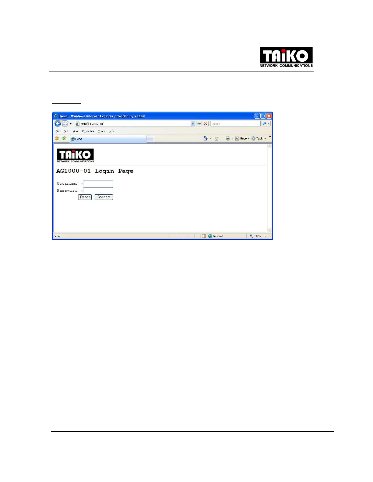
Section 3 Web Configuration
.1 Login
Enter the Web address of the confi uration pa e in the Internet Explorer address bar. Enter the correct
username and password to lo in.
Default factory settin :
IP / Web address : http://90.0.0.110/
Username : admin
Password : 1234
Inhaltsverzeichnis
Andere TAIKO Tor Handbücher


Beliebte Tor Handbücher anderer Marken

LST
LST M500RFE-AS Bedienungsanleitung

Kinnex
Kinnex Media Gateway Bedienungsanleitung

2N Telekomunikace
2N Telekomunikace 2N StarGate Bedienungsanleitung

Mitsubishi Heavy Industries
Mitsubishi Heavy Industries Superlink SC-WBGW256 Bedienungsanleitung

ZyXEL Communications
ZyXEL Communications ZYWALL2 ET 2WE Bedienungsanleitung

Telsey
Telsey CPVA 500 - SIP Bedienungsanleitung


