4
A standard 9-volt lithium or alkaline battery powers the TAG Detectors. Even though the
circuitry is constantly “ON” and sensing voltage, the battery should last for approximately
one year under normal use. We do recommend however, replacing the battery every six
months. If the instrument is to be stored for a year or more, remove the battery during storage.
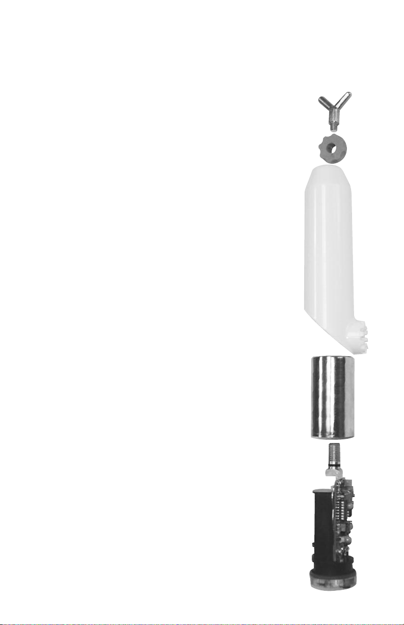
A universal spline adapter is built into the polycarbonate housing of the TAG Voltage
Detector units. Extension hotsticks are required for use at all times. Hotsticks are available
from HD Electric Company and must be used when placing the detector in contact with
any conductor.
ALL-CHEC SELF-TEST OPERATION
The All-Check self-test feature provides a full test of the battery, the electronic circuitry and
the audible and visual alarm.
NOTE: The All-Check self-test feature should be used both prior to and after testing the
conductor to confirm proper operation. In the instructions below, the numbers appearing
with the letter "A" refer to the TAG-200 Voltage Detector operating characteristics, the
numbers with the letter "B" refer to the TAG-200MR Voltage Detector and the numbers with
“C” refer to the TAG-330 Voltage Detector. The figures referenced are shown on page 5.
1A)Push and hold the test button on the inside of the polycarbonate housing to operate
the All-Check self-test procedure. The red (alarm) LED light will flash and the buzzer will
beep. After release of the button, the green LED light will illuminate for approximately
one to two (1-2) minutes. The unit is ready for operation. (Figure 1)
1B)Push and hold the test button on the inside of the polycarbonate housing to
operate the All-Check self-test procedure. The two red (alarm) LED lights will flash and
the buzzer will beep. After release of the button, no lights will remain on. (Figure 2)
1C)Push and hold the test button on the inside of the polycarbonate housing to operate
the All-Check self-test procedure. Three red (alarm) LED lights will flash and the buzzer
will beep. After release of the button, the green LED light will illuminate for approxi-
mately two (2) minutes. The unit is ready for operation. (Figure 3)
2) If pressing the test button does not cause the events listed in Step 1, the unit
should not be placed in operation. The battery may need replacement, see
Battery Replacement section (page 7). If changing the battery does not produce
the results shown in Step 1, remove the unit from service and send in for repair.
3) After completing the voltage detection on the conductor (see next section), always
confirm proper function of the TAG Detector by completing Step 1 again. If the self-test
does not function as above, DO NOT assume that the test results are correct. Re-test
the conductor, preferably with a different TAG Voltage Detector.
NOTE: When using the All-Check self-test feature, do not hold the housing of the TAG
Voltage Detector in your hand. This causes the detector's sensing field to be modified
and may distort the All-Check self-test ability to test. Hold the TAG Detector with a hot-
stick or hand hold at spline while pressing the red All-Check self-test button. Never use
the All-Check self-test if the TAG Detector is in contact with any voltage source.