Thermo Electron NESLAB System III Service-Handbuch

Visit our Web site at:
http://www.thermo.com/tchttp://www.thermo.com/tc
http://www.thermo.com/tchttp://www.thermo.com/tc
http://www.thermo.com/tc
Product Service Information, Applications
Notes, MSDS Forms, e-mail.
Voice Info: (800) 258-0830
NESLABNESLAB
NESLABNESLAB
NESLAB
SS
SS
System IIIystem III
ystem IIIystem III
ystem III
Heat ExchangerHeat Exchanger
Heat ExchangerHeat Exchanger
Heat Exchanger
Thermo Manual P/N U00678 Rev. 08/19/05
Installation-Operation-Installation-Operation-
Installation-Operation-Installation-Operation-
Installation-Operation-
Basic ServiceBasic Service
Basic ServiceBasic Service
Basic Service

© 2005 Thermo Electron Corp. 623-2087
All rights reserved. This document is for informational purposes only and is
subject to change without notice.
Thermo Electron Corporation
Control Technologies
25 Nimble Hill Road
Newington, NH 03801
(800) 258-0830 or
(603) 436-9444
Fax : (603) 436-8411
Control Technologies
Main Service Center
The Main Service Center is open
8:00 am to 5:00 pm (Eastern
Time), Monday through Friday.
Thermo NESLAB
25 Nimble Hill Road
Newington, NH 03801
(800) 258-0830 or
(603) 436-9444
Fax : (603) 436-8411
West Coast
355 River Oaks Parkway, Door 10
San Jose, CA 95134
United States
Tel : (800) 423-7831 or
(408) 965-6050
Fax : (408) 965-6051
South
8711 Burnet Road
Suite F69
Austin, TX 78757-7065
(512) 459-2167
Fax : (512) 459-1731
Netherlands
Takkebijsters 1
Breda 4817 BL
Netherlands
Tel : +31 76 587 9888
Fax : +31 76 579 5610
Germany
Dieselstrasse 4
Karlsruhe 76227
Germany
Tel : +49 (0) 721 4094 0
Fax : +49 (0) 721 4094 300
France
16 Avenue du Québec - Silic 765
Courtaboeuf Cédex 91963
France
Tel : 33 (0) 1 60 92 48 00
Fax : 33 (0) 1 60 92 49 00
United Kingdom
Ion Path, Road Three
Winsford CW7 3GA
United Kingdom
Tel : +44 1606 548749
Fax : +44 1606 548712

- 1 -
System III Liquid to Liquid Heat Exchanger
Instruction and Operation Manual
Table of Contents
PREFACE Compliance ............................................................................................ 3
WEEECompliance................................................................................. 3
Unpacking .............................................................................................. 4
Warranty................................................................................................. 4
NES-care................................................................................................ 4
After-saleSupport ................................................................................... 4
Feedback ............................................................................................... 4
SECTION I
Safety Warnings ................................................................................................ 5
SECTION II
GeneralInformation Description ............................................................................................. 6
Specifications ......................................................................................... 6
SECTION III
Installation Site......................................................................................................... 8
FacilityWaterRequirements................................................................... 8
ElectricalRequirements.......................................................................... 9
VoltageSelection ................................................................................... 9
PlumbingRequirements.......................................................................... 9
Fluids ..................................................................................................... 10
FillingRequirements ............................................................................... 11
AutomaticRefillDevice(Optional) ........................................................... 11
FlowControl ........................................................................................... 11
AutoRestart ........................................................................................... 11
SECTION IV
Operation StartUp.................................................................................................. 12
TemperatureController............................................................................ 13
SetupLoop ............................................................................................. 14

- 2 -
SECTION V
Maintenance& Service ServiceContracts ................................................................................... 15
PumpStrainer ........................................................................................ 15
Facility Water Strainer ............................................................................ 15
Algae ...................................................................................................... 16
Configuration........................................................................................... 16
VoltageSelection ................................................................................... 16
PressureReliefValve .............................................................................. 16
FaultInterlockContact............................................................................ 17
Fuses ..................................................................................................... 17
PhaseRotation ....................................................................................... 17
PumpMotorOverloadProtector .............................................................. 17
DisplayingSoftwareVersion ................................................................... 18
SECTION VI
Troubleshooting ErrorCodes ............................................................................................ 19
PoorTemperatureStability ..................................................................... 20
ServiceAssistance ................................................................................. 20
Parts List................................................................................................ 20
SECTION VII
Diagrams TUPumpFlowDiagram .......................................................................... 21
FrontView .............................................................................................. 22
RearView ............................................................................................... 22
LargeVolumeUnits ................................................................................ 23
APPENDIX Water Quality and Standards
WARRANTY

- 3 -
Preface
Compliance Products tested and found to be in compliance with the requirements defined in the EMC
standardsdefined by89/336/EECas wellasLow VoltageDirective(LVD) 73/23/EECcan be
identified by the CE label on the rear of the unit. The testing has demonstrated compliance with
thefollowingdirectives:
LVD,73/23/EEC ComplieswithUL3101-1:93
EMC,89/336/EEC EN 55011, Class A Verification
EN50082-1:1992
IEC1000-4-2:1995
IEC1000-4-3:1994
IEC1000-4-4:1995
Forany additionalinformation referto theLetter ofCompliancethat shippedwith theunit
(DeclarationofConformity).
WEEE Compliance
This product is required to comply with the European Union’s Waste Electrical & Electronic
Equipment(WEEE) Directive2002/96/EC. It ismarked withthe followingsymbol:
ThermoElectron has contracted withone or morerecycling/disposal companies ineach EU
Member State, and this product should be disposed of or recycled through them. Further
informationon ThermoElectron’scompliance withthese Directives,the recyclersinyour
country, and information on Thermo Electron products which may assist the detection of
substancessubject totheRoHS Directiveare availableat:
www.thermo.com/WEEERoHS

- 4 -
After-saleSupport
ThermoElectronCorporationiscommitted tocustomerservice bothduringandafter thesale.If
youhave questionsconcerningthe operationofyour unit,contact ourSalesDepartment. Ifyour
unitfails to operateproperly, or ifyou have questionsconcerning spare parts,contact our
CustomerServiceDepartment.Beforecalling,pleaseobtainthefollowinginformation:
- BOM number
- Serial number
-Softwareversion
The BOM and serial number are on a label on the rear of the unit. To display the software
versionseepage17.
Unpacking Retain all cartons and packing material until the unit is operated and found to be in good
condition.If the unitshows externalor internal damagecontact thetransportation companyand
file a damage claim. Under ICC regulations, this is your responsibility.
Warranty Unitshaveawarrantyagainstdefectivepartsandworkmanshipforonefullyearfromdateof
shipment. See back page for more details.
NES-care Extended
Warranty Contract
•Extendpartsand laborcoverageforan additionalyear.
•Worry-freeoperation.
• Control service costs.
•Eliminate theneed togeneraterepair orders.
• No unexpected repair costs.
Othercontractoptionsareavailable.PleasecontactThermousformoreinformation.
Feedback We appreciate any feedback you can give us on this manual. Please e-mail us at
[email protected].Besuretoincludethemanualpartnumberandtherevisiondate
listedonthe frontcover.

- 5 -
Section I Safety
Warnings
Make sure you read and understand all instructions and safety precautions
listed in this manual before installing or operating your unit. If you have any
questions concerning the operation of your unit or the information in this
manual, contact our Sales epartment.
Performance of installation, operation, or maintenance procedures
other than those described in this manual may result in a hazardous
situation and may void the manufacturer s warranty.
Observe all warning labels.
Never remove warning labels.
Never operate damaged or leaking equipment.
Always turn off the unit and disconnect the line cord from the power
source before performing any service or maintenance procedures, or
before moving the unit.
Always empty the reservoir before moving the unit.
Never operate equipment with damaged line cords.
Never operate without fluid.
Refer service and repairs to a qualified technician.
In addition to the safety warnings listed above, warnings are posted throughout
the manual. These warnings are designated by an exclamation mark inside an
equilateral triangle with text highlighted in bold print. Read and follow these
important instructions. Failure to observe these instructions can result in
permanent damage to the unit, significant property damage, or personal injury
or death.
- 6 -
Section II General Information
Description
The NESLAB System III Liquid to Liquid Heat Exchanger is designed to
remove heat from water-cooled instruments. The unit consists of a heat
exchanger, recirculation pump, PVC reservoir, and a microprocessor controller.
Specifications
Temperature Range
Temperature Stability
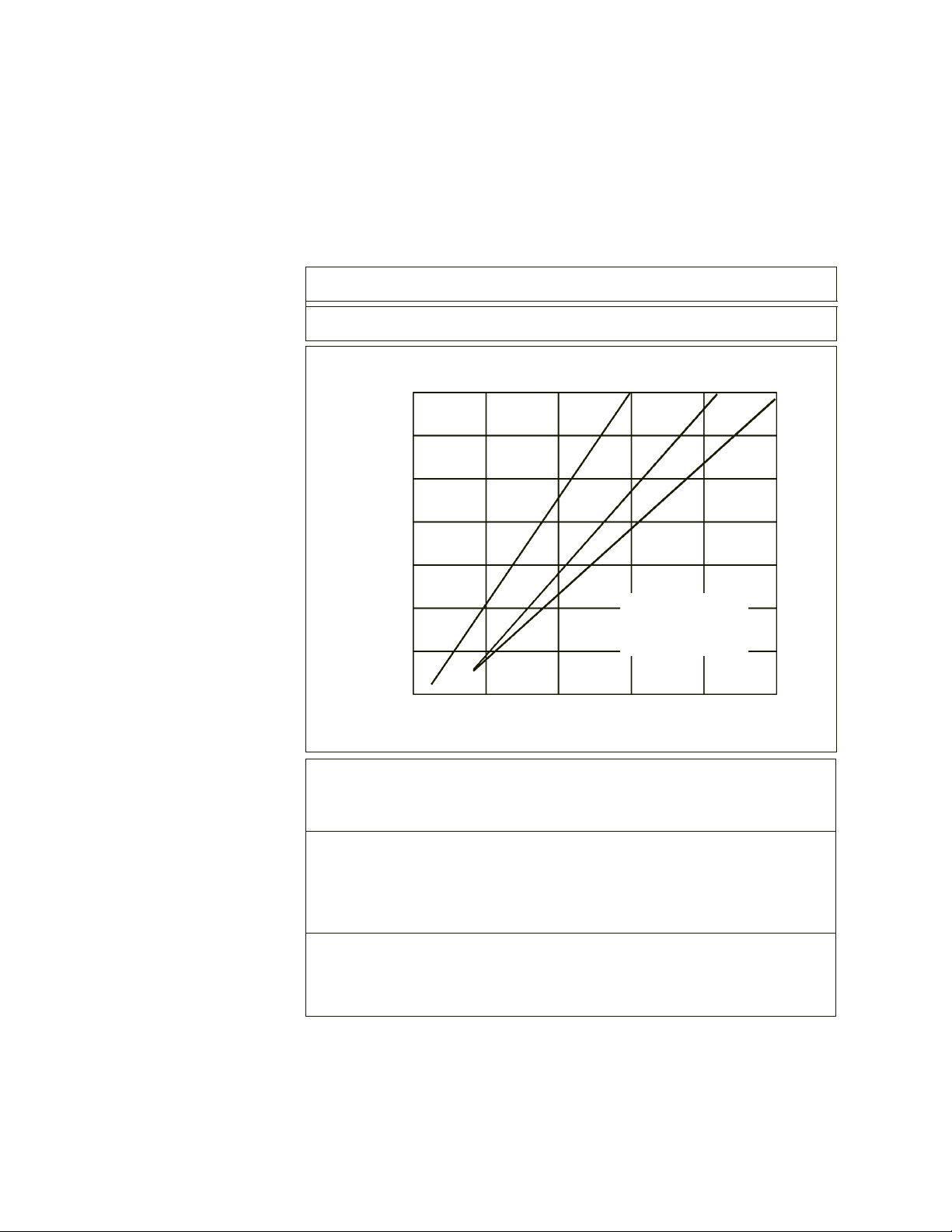
Cooling Capacity1
Heat Removal (KW)
510152025
A= 6gpm pump flow
B= 10 gpm pump flow
C= 12gpm pump flow
AB
C
70
60
50
40
30
20
10
acility Water low GPM
1 2 2.4 3.5 5 6 8 10
Pressure Drop (PSI)
Reservoir Volume2
Gallons
Liters
Dimensions3
(H x W x D)
In hes
Centimeters
Shipping Weight4
Pounds
Kilograms
1.25
4.7
20¾ x 173/8 x 27
52.7 x 44.1 x 68.6
206
93.4
1. Cooling capacity is based in a 10°C difference between the temperature of the cooling
water supply and the cooling fluid flowing from the System III
to the instrument being cooled (see
Section III, acility Water Requirements). Pressure drop obtained with the System III modulating
valve fully open.
2. Larger volume reservoir units are available.
3. Units with CP-55 and TU-3 pumps. Other larger volume units measure 33¾ x 23 x 27¼
(85.7 x 58.4 x 69.2). or complete dimensions see pages 22-23.
4. Approximate. Larger volume units weigh approximately 355 pounds (161 kilograms).
+5°C to +40°C
±1.0°C
- 7 -
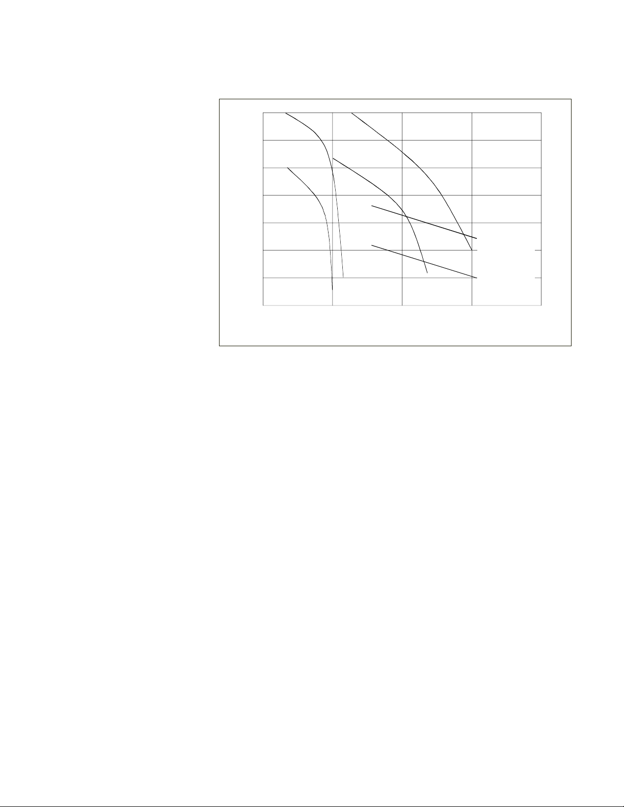
Pressure (psi)
low (gallons/minute)
70
60
50
40
30
20
10
5101520
A
D
C
B
A=TU-7, 60Hz
B=TU-7, 50Hz
C=TU-3, 60Hz
D=TU-3, 50Hz
E=CP-55, 60Hz
=CP-55, 50HZ
5.TU-7, TU-8, and TU-9 pumps require 3Ø power.
6.TU-5 pumps are rated 9 gpm @ 50 psi, TU-6 pumps are 12 gpm @ 50 psi, TU-8 pumps
are 20 gpm @ 50 psi, and TU-9 pumps 23 gpm @ 50 psi.
Pump Capacity5,6
E

- 8 -
Section III Installation
Site
The unit should be located in a laboratory or clean industrial environment with
easy access to a facility cooling water supply and a drain. Never place the unit
in a location where excessive heat, moisture, or corrosive materials are
present.
Refer to the pump label on the rear of the unit to identify the specific type of
pump in your unit. Units with a TU-7, TU-8 or TU-9 pump are equipped with a
pump motor fan. The fan is used to cool the pump motor and prevent the motor
from overheating. Air is drawn through the front of the unit and is discharged
through the rear of the unit. A minimum clearance of 6 inches (0.15 meters) at
the front and rear of the unit is necessary for ventilation.
Facility Water
Req irements
Limit the facility water inlet pressure to less than 150 psi (10,2 Bar) and
limit the facility water inlet pressure to outlet pressure differential
across the System III to less than 35 psid (2,4 Bar).
Refer to the Cooling Capacity chart in Section II, Specifications. The flow rate of
the cooling water supply must meet or exceed these requirements for the unit
to operate at its full rated capacity. If the cooling water does not meet these
standards, the cooling capacity will be derated. The chart is based on a
difference between the temperature of the cooling water supply (House Water)
and the cooling fluid flowing from the System III to the instrument being cooled.
As the heat load increases, the required flow rate of the cooling water supply
increases. For example, on a System III with a 6 gpm pump flow, if the heat
load is 12 kilowatts, approximately 3 gpm of cooling water flow is required to
remove the heat. However, if the heat load is increased to 36 kilowatts, about 8
gpm of cooling water flow is required.
The flow meter on the front of the unit does not measure the flow rate of the
cooling water supply. The flow meter measures the flow rate of the cooling
fluid returning to the instrument being cooled.
Inhaltsverzeichnis
Beliebte Heizung Handbücher anderer Marken


Empire Heating Systems
Empire Heating Systems WCC65 Bedienungsanleitung

Wetekom
Wetekom 92 86 43 Bedienungsanleitung

Desa
Desa SPC170-F Bedienungsanleitung

Watlow
Watlow Watrod Electric Tubular Heaters Bedienungsanleitung

Haverland
Haverland ECO-DRY GPS Series Stücklistenhandbuch

Stelpro
Stelpro ASILVC2060 Series Bedienungsanleitung